Previous Next

MacPherson Struts

REMOVAL & INSTALLATION

Except RX-7, 929 and 1988–89 323, 626 and MX-6
  1. Remove the wheel cover and loosen the lug nuts.
  2. Raise the front of the vehicle and support it with jackstands. Do not jack it or support it by any of the front suspension members. Remove the wheel.
  3. On rear wheel drive models, remove the caliper and disc as described in Section 9.
  4. Support the strut from underneath, then unfasten the nuts which secure the upper shock mount to the top of the wheel arch. Disconnect the brake line from the strut.

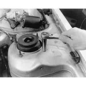
    Fig. 1: From inside the engine compartment, unfasten the nuts which secure the upper shock mount

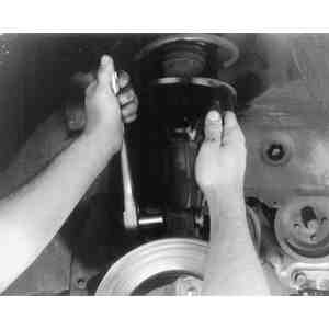
    Fig. 2: Use two wrenches to loosen the bolts which secure the lower end of the shock absorber assembly

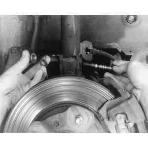
    Fig. 3: Remove the nuts, washers and bolts . . .

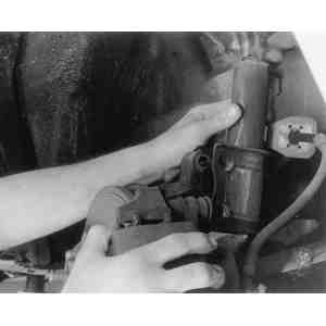
    Fig. 4: . . . then separate the shock absorber from the steering knuckle arm

  5. Remove the two bolts that secure the lower end of the shock to the steering knuckle arm.
  6. Remove the shock and coil spring as a complete assembly.
  7. Mount the strut (shock/spring) assembly in a vise. Protect the shock tube by placing a piece of soft metal on either side between the tube and vice jaws. Compress the coil spring with a spring compressor.
  8. Hold the upper end of the shock piston rod with a pipe wrench and unfasten the locknut.
  9. Remove the parts from the top of the shock absorber in the order shown in the appropriate illustration.

    CAUTION
    When removing the spring compressor from the coil spring, do so gradually so that spring tension is not released all at once.

  10. During installation, tighten the nut on top of the piston rod to 10 ft. lbs. (14 Nm) on most rear wheel drive models. On GLCs with front wheel drive and 1979–82 626s, torque the piston rod nut to 47–59 ft. lbs. (64–80 Nm). On front wheel drive GLCs and 323s, torque the piston rod nut to 41–49 ft. lbs. (56–66 Nm), and the mounting block-to-suspension tower to 17–21 ft. lbs. (23–28 Nm). On 1983–87 626s, torque the piston rod nut to 47–59 ft. lbs. (64–80 Nm), the mounting block-to-suspension tower nuts to 16–21 ft. lbs. (21–28 Nm), and the lower strut bolts to 69–86 ft. lbs. (93–117 Nm).

    On 1983–87 front wheel drive models, there is a mark or hole in the mounting block. Be sure it faces the inside of the vehicle when positioning the block.

    NOTE: If a new coil spring is being fitted, match it with an adjusting plate of the correct thickness to obtain equal road clearance on both sides. Do not use more than two adjusting plates on a side.

1988–89 323
  1. Loosen the front lug nuts, then raise the front of the vehicle and support it safely. Remove the front wheels.
  2. On vehicles equipped with Adjustable Shock Absorbers (ASA), peel the rubber cap from the ASA actuating unit to expose the retaining screws. Disengage the electrical connector from the actuating unit. Loosen the retaining screws and remove the actuating unit from the mounting block.
  3. Remove the nuts from the strut mounting block. Remove the brake line clip and separate the brake line from the strut tower mounting tab. Position the brake line off to the side.
  4. Remove the two bolts from the shock tower mounting bracket and remove the strut assembly.
  5. To install, position the strut assembly onto the suspension tower so that the white dot on the mounting block faces toward the inside of the vehicle. Maneuver the shock tower mounting bracket onto the steering knuckle and insert the two bolts. Install the mounting block nuts and make them finger-tight. Torque the shock tower mounting bolts to 69–86 ft. lbs. (93–117 Nm). Place the brake line into the mounting tab on the shock tower and push the brake line clip to hold it in place. Torque the mounting block nuts to 22–27 ft. lbs. (30–37 Nm).
  6. On ASA equipped vehicles, place the actuating unit onto the mounting block and install the retaining screws. Torque the retaining screws to 14–21 ft. lbs. (19–28 Nm). Fasten the electrical connector and install the rubber cap.
  7. Install the front wheels and lower the vehicle.
1988–89 626 and MX-6
  1. Loosen the front lug nuts, then raise the front of the vehicle and support it safely. Remove the front wheels.
  2. Remove the brake line clip and separate the brake line from the strut tower mounting tab. Position the brake line off to the side.
  3. On vehicles equipped with ABS, use a long extension to remove the ABS harness bracket bolt. Remove the harness and bracket, then position them off to the side and out the way. On vehicles equipped with Auto Adjusting Suspension (AAS), peel the rubber cap from the AAS actuating unit to expose the retaining screws. Disengage the electrical connector from the actuating unit. Loosen the retaining screws and remove the actuating unit from the mounting block.
  4. Remove the two nuts and one bolt and remove the ignition coil bracket from the mounting block studs. Remove the lower clinch bolts and mounting block nuts. Remove the strut assembly from the vehicle. Remove the adjust plate from the mounting block.

    To install:

  5. Place the adjusting plate on the mounting block. Position the strut assembly onto the suspension tower so that the white dot on the mounting block faces the towards the inside of the vehicle. Maneuver the shock tower mounting bracket onto the steering knuckle and insert the two bolts. Install the mounting block nuts and make them finger-tight. Torque the shock tower mounting bolts and the mounting block nuts to 69–86 ft. lbs. (93–117 Nm).
  6. Connect the ignition coil bracket to the mounting block. On AAS equipped vehicles, place the actuating unit onto the mounting block and install the retaining screws. Torque the retaining screws to 14–21 ft. lbs. (19–28 Nm). Engage the electrical connector and install the rubber cap. On ABS equipped vehicles, connect the ABS harness and bracket to the shock tower, then torque the mounting bolt to 12–17 ft. lbs. (16–23 Nm).
  7. Place the brake line into the mounting tab on the shock tower and push the brake line clip to hold it in place. Install the front wheels and lower the vehicle.
929
  1. Loosen the front lug nuts, then raise the front of the vehicle and support it safely. Remove the front wheels.
  2. Remove the brake line clip and separate the brake line from the strut tower mounting tab. Position the brake line off to the side.
  3. On vehicles equipped with Auto Adjusting Suspension (AAS), remove the AAS harness bracket bolt. Remove the harness and bracket, then position them off to the side and out the way. Disengage the electrical connector from the AAS actuating unit. Peel the rubber cap from the AAS actuating unit.
  4. Remove the lower clinch bolts and mounting block nuts. Remove the strut assembly from the vehicle.
  5. To install, position the strut assembly onto the suspension tower so that the white dot on the mounting block faces the towards the inside of the vehicle. Maneuver the shock tower mounting bracket onto the steering knuckle and insert the two bolts. Install the mounting block nuts and make them finger-tight. Torque the shock tower mounting bolts to 69–86 ft. lbs. (93–117 Nm) and the mounting block nuts to 23–33 ft. lbs. (31–45 Nm).
  6. On AAS equipped vehicles, engage the electrical connector and install the rubber cap. Connect the AAS harness and bracket to the shock tower, then torque the mounting bolt to 12–17 ft. lbs. (16–23 Nm).
  7. Place the brake line into the mounting tab on the shock tower and push the brake line clip to hold it in place. Install the front wheels and lower the vehicle.
RX-7

The RX-7 uses a strut-type front suspension in which shock absorber and coil spring are mounted on a rotating strut. (This assembly takes the place of the conventional upper arm and ball joint.) The strut is fastened to the upper inside fender well and to the lower arm. The front suspension is equipped with both tension rods and a stabilizer bar.

  1. Raise the front of the car and support it safely
  2. Remove the front wheel, brake caliper and rotor assembly (see Section 9).
  3. On 1979–85 models, remove the brake backing plate. Remove the brake fluid hose attaching clip on the strut and remove the two bolts attaching the strut to the steering knuckle/lower arm assembly.

    Fig. 5: Note the location of the triangular mark before removing the strut

  4. Open the engine compartment and note the position of a triangular mark on the top of the strut (it must be installed in the same location it is now facing). On 1986–89 models, there is white dot painted on the mounting block instead of a triangle. During installation, the dot must face towards the front inside of the engine.
  5. On 1979–85 models, after installing the strut, measure the distance from the ground to the center of each headlight. If the distance on each side is not within 0.59 in. (15mm) of the other side, adjust the height with adjusting plates available from your local Mazda dealer. Do not use more than two adjusting plates on each side.
  6. Tighten the upper strut attaching nuts to 17–22 ft. lbs. (23–30 Nm) and the knuckle arm to strut bolts to 43–51 ft. lbs. (58–69 Nm).

Previous Next