NOTE: This procedure requires many special tools. Check on
the availability of these before starting. It may be cheaper for you to have
some aspects of the work done professionally than to buy certain tools.
- Follow the necessary steps of the disc brake rotor removal & installation
procedure, as described in Section 9 of this manual, in order to remove the
rotor from the hub.
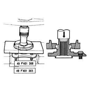
- Arrange the bearing remover (Mazda tool No. 49–F401–365 or equivalent)
and attachment B (49–F401–368 or equivalent) as shown and, with
a press, remove the outer bearing's inner race. Make sure the hub does not
fall and get damaged.
- Use a brass drift and a hammer to strike the edge of the outer race and
remove it. Tap all around the race, forcing it out in small increments.
- Wash parts in solvent before inspecting. Inspect the knuckle for damage,
rust in the bearing bore, or a bad dust cover or seal.
- If the dust cover must be replaced, tap it in place with a hammer and a
pipe of 3.19 in. (81mm) in diameter. Make sure the dust cover is properly
positioned.
- Fit the bearing outer race into the knuckle with a brass rod and hammer.
Make sure it seats in the knuckle.
- Check the bearing preload by installing a spacer selector (Mazda tool No.
49–B001–727 or equivalent) in a vise and assembling to it the
steering knuckle along with the original spacer. Bearing preload (the torque
required to start it turning) should be 1.7–6.9 inch lbs (0.2–0.8
Nm). This is equivalent to 0.5–1.9 lbs. measured by a spring scale at
the caliper mounting hole of the knuckle. The tool must be tightened to 145
ft. lbs. in 36 ft. lb. increments. As each increment is completed, rotate
the bearing to seat it properly, make sure it turns smoothly, then repeat
the tightening operation until 145 ft. lbs. is reached. Make sure you again
turn the bearing to seat it before reading the preload.
- If the preload is outside specifications, increase the thickness of the
spacer to decrease it if it is too high; decrease the thickness of the spacer
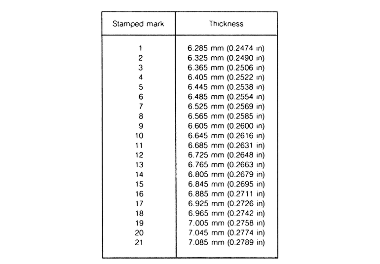
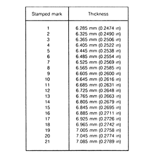
to increase the preload if it is too low. There is a mark stamped on the outer
periphery of the spacer that represents its thickness (see the table). A change
in thickness of one number changes the preload 1.7–3.5 inch lbs. (0.2–0.4
Nm).
- Substitute a new spacer, and repeat the preload measuring procedure until
the preload meets specification.
- Apply grease to the lip of a new outer oil seal and gently tap it in with
a plastic hammer. Make sure the surface is flush with the knuckle when it's
installed.
- In the same way, but using an appropriate installer (Mazda tool No. is 49
B001 795) install a new inner seal.
- Fill these areas with lithium grease meeting NGLI No. 2 specification: the
spaces between the bearing rollers; the space between the inner and outer
bearings; the space between each bearing and the adjacent seal.
- Using the spacer selector described above and a press, install the wheel
hub into the knuckle. This requires as much as 6,613 lbs. pressure.
- Install the knuckle to the suspension system in reverse of the removal procedure,
using a new driveshaft locknut, and observing the following torque figures:
- Rotor-to-hub bolts: 33–39 ft. lbs.
- Knuckle-to-strut bolts: 58–86 ft. lbs.
- Knuckle-to-ball joint: 33–39 ft. lbs.
- Lower arm-to-ball joint: 69–96 ft. lbs.
- Knuckle and brake caliper: 41–48 ft. lbs.
- Driveshaft locknut: 116–174 ft. lbs.
- Knuckle-to-tie rod end: 28–32 ft. lbs.
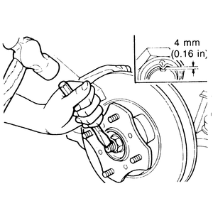
Make sure to stake over the driveshaft locknut with a dull punch until
it is indented into the groove in the shaft at least 0.16 in. (4mm). Use
a new cotter pin for the tie rod end nut.
| Fig. 1: Spacer thickness selection chart — GLC
and 1986–87 323
|
NOTE: This procedure requires many special tools. Read the
procedure over first, and determine availability of the special tools before
you start work. In some cases, it may be less expensive to have certain operations
performed by a local repair shop than to purchase the appropriate tools.
- Loosen the lug nuts. Raise the vehicle and support it safely. Remove the
tire and wheel.
- Raise the staked tab from the hub center nut, remove the nut from the axle.
Apply the brake to help hold the rotor while loosening the nut.
- Using ball joint puller tool 49-0118-850C or equivalent, separate the tie
rod end from the steering knuckle. Disconnect the horseshoe clip that retains
the brake line to the strut. On the 626 and MX6, remove the stabilizer bar
control link from the control arm as described previously in this section.
- Remove the mounting bolts that hold the caliper assembly to the knuckle.
Do not allow the caliper to be supported by the brake hose; support it with
wire.
- Remove the through-bolt and nut that retains the lower ball joint to the
steering knuckle and disconnect the ball joint.
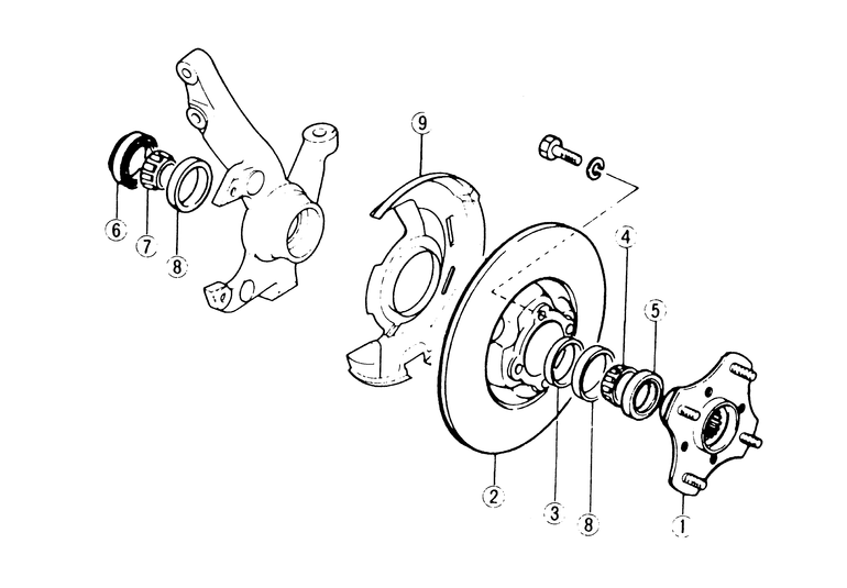
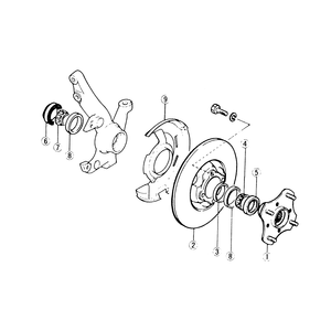
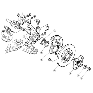
| Fig. 2: Front hub, knuckle and bearing assembly — 323
|
| Fig. 3: Front hub, knuckle and bearing assembly — 626
|
| Fig. 4: Removing the outer front wheel bearing's
inner race — 1983–87 626
|
- Remove the two bolts and nuts retaining the strut to the steering knuckle.
Separate the steering knuckle and hub from the strut and axle shaft. On 626
and MX-6 with ABS, remove the speed sensor from the strut bracket.
- The hub is pressed through the wheel bearings into the knuckle. Removal/replacement
of the hub requires wheel hub puller tool No. 49-G030-725/49-G030-727 (or
equivalent) for the 1983–87 626 and 323, or Nos. G49-G033-102, 104 and
105 (or equivalent) for 1988–89 626 and MX-6.
NOTE: On 1988–89 626 and MX-6, if there is an inner
race on the front wheel hub, grind or machine a section of the bearing inner
race to approximately 0.02 in. (0.5mm) and remove it with a small cold chisel.
- Remove the inner oil seal and bearing. Remove the outer bearing using a
press and tool 49-G030-725/49-G030-728 for the 1983–87 626 and 323 in
order to remove the bearing from the steering knuckle. Drive the outer and
inner race from the knuckle with a brass drift and hammer. On 1988–89
323, remove the outer bearing race with tools 49-B092-372 and 49-F401-366A
and then withdraw the outer oil seal from the front hub. On 1988–89
323, remove the bearing outer race with tool 49-FT01-361 and a press and remove
the wheel bearing. On 1988–89 626 and MX-6, press the bearing from the
hub using tools, 49-G033-102, 104 and 106.
- Inspect the knuckle for cracks, heat damage, or rust. The dust cover may
be left in place unless it is damaged. If it must be replaced, note its position
before removal or scribe alignment marks. Then, install a new one using a
pipe about 3.19 in. (81mm) in diameter and a hammer or press. Replace the
oil seal if it is damaged or worn at the contact surface.
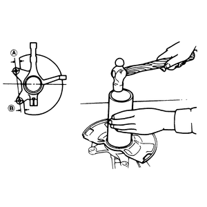
| Fig. 5: Position the dust cover on the 626 steering
knuckle as shown
|
| Fig. 6: Staking the front hub locknut
|
- Inspect the oil seal for proper position. If it has moved upward, press
it back into position. The knuckle should be placed so it is securely supported
by its center, that is, the center of the knuckle should be aligned with the
spindle of the press. Then, press in the new bearing with a piece of pipe
about 2.6 in. (66mm) in diameter bearing only on the outer race.
- Install new inner and outer races as required. Make sure that the edge of
the race contacts the steering knuckle. Pack the inner and outer bearing with
grease and install in knuckle. Use tool 49-G030-728 for the 1983–87
626 and 323 to press the hub into the steering knuckle. On 1988–89 323,
use tool 49-V001-795 to seat the bearing in the hub. On 1988–89 626
and MX-6, use tools 49-G030-797, 49-F027-007 and 49-H026-103 to install the
wheel bearing.
- On 1983–87 models, measure the preload with a scale connected to the
caliper mounting hole on the knuckle. Various spacers are available to increase
or decrease the preload. Preload should be 1.7–6.9 ft. lbs.
- On 1988–89 323, measure/adjust the preload as follows:
- Insert the bearing and spacer into the steering knuckle and install
tool 49-B001-727. Tighten the tool to 145 ft. lbs.
- Connect a spring scale to caliper mounting bolt hole on the dust cover
and pull on the scale to measure the bearing preload (starting rotation
torque). This preload should be 0.53–2.55 lbs. for 13 in. wheels
and 0.48–2.35 lbs. for 14 in. wheels. When tightening the preload
tool, torque in 36 ft. lb. increments.
- If the preload is not within specification, spacers are available in
a variety of thicknesses to adjust it. Increase the spacer thickness when
the preload is too high and decrease the thickness when preload is too
low.
- Install the inner and outer grease seals. Press fit the hub through the
bearings into the knuckle.
- Installation of the knuckle and hub is in the reverse order of removal.
Always use a new axle locknut and cotter pin. On 323s, torque the axle shaft
locknut to 116–174 ft. lbs. On the 626 and MX6 torque the locknut to
116–124 ft. lbs. Stake the locknut after tightening. Use a small cold
chisel to stake the locknut tab. After the tab is staked, make sure that at
least 0.16 in. (4mm) of the tab is in the groove.