Unfasten the steering wheel attaching nut, and remove the wheel with a puller.
Unfasten the attaching screws, and remove the upper and lower (or right
and left) steering column covers.
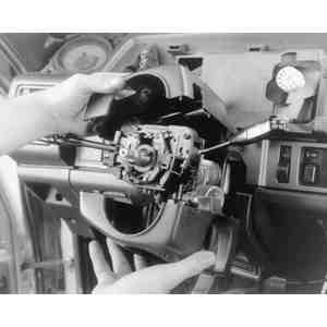
Fig. 1: Separate the two column covers to expose
the combination switch
Detach the connector for the combination switch or, if the ignition switch
is being replaced, detach the connectors for both the ignition and combination
switches.
Remove the retaining ring from the steering column (not required on 1983–89
626).
Unfasten the retaining screw, then remove the combination switch.
To install:
Install the combination switch and secure with the retaining screw.
Install the steering column retaining ring (if so equipped).
Connect all combination or ignition switch connectors.
Install the steering column covers with their retaining screws. On 1988–89
626, MX-6 and 929, once the combination switch is in place and the covers
are installed, set the front wheels straight, then align the combination switch
and steering angle sensor marks as shown.
Install the steering wheel and horn cap/ornament.
Connect the negative battery cable and check all the functions of the combination
switch for proper operation.