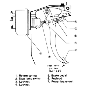
- Detach the wiring from the brake light switch terminals.
- Loosen the locknut on the switch.
- Turn the switch until the distance between the pedal and the floor is:
- GLC with rear wheel drive and manual transmission: 7.50 in. (190mm)
- GLC with rear wheel drive and automatic transmission: 7.67 in. (195mm)
- GLC with front wheel drive: 8.50 in. (215mm)
- 626: 8.67 in. (220mm)
- Tighten the locknut on the switch, then attach the wiring.
- Loosen the locknut located on the pushrod.
| Fig. 1: Brake pedal and related components — 1978–82
GLC and 626

|
- Rotate the pushrod until 0.28–0.35 in. (7–9mm) of pedal free
travel is obtained.
- Tighten the pushrod locknut.
- Remove the blower duct. Measure the pedal height (distance from the center
of the brake pedal's upper surface to the firewall, behind the insulation).
It should be 8.43–8.62 in. (214–219mm).
- If adjustment is necessary, detach the brake lamp switch electrical connector,
then loosen the switch locknut. Turn the switch so that it does not contact
the pedal.
- Loosen the locknut, then turn the operating rod until the pedal height is
correct.
- Depress the brake pedal several times, in order to eliminate vacuum in the
line.
- Gently depress the pedal by hand and check the free-play. If necessary,
turn the operating rod until the pedal free-play is 0.28–0.35 in. (7–9mm).
Tighten the operating rod locknut.
- Turn the brake lamp switch until it contacts the pedal, and then an additional 1⁄2 turn.
Tighten the locknut, then attach the electrical connector. Install the blower
duct.
- Remove the under cover from the instrument panel. Detach the brake lamp
switch electrical connector.
- Loosen the brake lamp switch locknut, then turn the switch outward until
the pedal does not touch it.
- Loosen the operating rod locknut, then turn the rod to adjust the pedal
height to 8.46–8.66 in. (215–220mm) on the GLC, or 8.62–8.82
in. (219–224mm) on the 323. Measure from the center of the brake pedal's
upper surface to the firewall (behind the insulation). Fasten the position
of the operating rod with the locknut.
- Screw the brake lamp switch inward until it just touches the pedal, and
then an additional 1⁄2 turn.
- Check the free-play in the brake pedal. It should be 0.28–0.35 in.
(7–9mm) on the GLC, or 0.16–0.28 in. (4–7mm) on the 323.
If necessary, adjust the free-play by loosening the operating rod locknut
and turning the rod. Tighten the locknut.
- Fasten the brake lamp switch electrical connector. Install the instrument
panel under cover.
Measure the pedal height (distance from the center of the brake pedal's upper
surface to the firewall, behind the insulation). It should be 8.43–8.62
in. (214–219mm) for 323s, 8.54–8.74 in. (217–222mm) for 626/MX-6s,
8.23–8.43 in. (209–214mm) for 929s equipped with a manual transmission,
or 8.03–8.23 in. (204–209mm) for 929s with an automatic transmission.
If the distance is not as specified, perform the following adjustments (see
illustration):
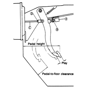
- Detach the electrical connector from brake light switch A.
- Loosen locknut B and turn switch A until
it does not contact the pedal.
- Loosen locknut D and turn operating rod C to
adjust the pedal height as specified.
| Fig. 2: Brake pedal height and free-play adjustment — 1988–89
323, 626, MX-6 and 929; 1979–89 RX-7

|
- Depress the brake pedal several times by hand and check the free-play. (Free-play
is the amount of brake pedal travel before the brake booster begins to operate.)
There should be 0.16–0.28 in. (4.0–7.0mm) of play. Loosen the
operating rod locknut, then turn the rod to adjust free-play until it is correct.
- After the free-play is correct, tighten the operating rod locknut D.
- Turn the brake light switch until it makes contact with the pedal, and then
an additional 1⁄2 turn.
Tighten the locknut, then attach the electrical connector to the switch.
Measure the pedal height (distance from the center of the brake pedal's upper
surface to the firewall, behind the insulation). It should be 7.48–7.68
in. (190–195mm) for 1979–85 models, or 8.07–8.27 in. (205–210mm)
for 1986–89 models. If the distance is not as specified, perform the following
adjustments (see illustration):
- Detach the connector from brake light switch A.
- Loosen locknut B and turn switch A until
it does not contact the pedal.
- Loosen locknut D and turn operating rod C to
adjust the pedal height as specified.
- Depress the brake pedal several times by hand and check the free-play. There
should be 0.28–0.35 in. (7.0–9.0mm) for 1979–85 models,
or 0.16–0.28 in. (4.0–7.0mm) of play for 1986–89 models.
Loosen the operating rod locknut and turn the rod to adjust the pedal play
until it is correct.
- After the free-play is within specifications, tighten operating rod locknut D.
- Turn the brake light switch until it makes contact with the pedal, then
tighten the locknut. Attach the electrical connector to the switch.

