Previous Next

Brake Shoes

REMOVAL & INSTALLATION

Rear Wheel Drive Models

CAUTION
Brake shoes may contain asbestos, which has been determined to be a cancer causing agent. Wear an approved filter mask or respirator whenever working around brakes, to avoid inhaling dust from any brake surface. Never clean brake components with compressed air! Instead, use a commercially available brake cleaning fluid.

NOTE: When removing and installing brake shoes, work on one side at a time so that, if necessary, you can refer to the undisturbed assembly on the other side for reference.

  1. Perform the brake drum removal procedure, as previously detailed. Make sure that the parking brake is fully released.
  2. Clean the dirt from the brake components with an aerosol brake cleaner.
  3. Remove the return springs from the upper side of the shoe using a brake spring removal tool.
  4. Remove the return springs from the lower side of the shoes in the same manner as Step 3.
  5. Remove the shoe retaining spring by compressing the retaining spring while turning the pin 90 degrees.
  6. Withdraw the primary shoe and the parking brake link.
  7. Disengage the parking brake lever from the secondary shoe by unfastening its retaining clip.

    Fig. 1: Rear drum brake components — RX-7

  8. Remove the secondary shoe.
  9. Inspect the linings and replace them if they are worn, badly burned or saturated with oil or grease. See the Brake Specifications chart in this section.

    To install:

  10. Lubricate the threads of the adjusting screw, the sliding surfaces of the shoes, and the backing plate flanges with a small quantity of grease.

    WARNING
    Be careful not to get oil or grease on the lining surfaces.

  11. Position the parking brake lever on the secondary shoe and secure with its retaining clip.
  12. Install the eye of the parking brake cable through the parking brake lever.
  13. Fit the link between the shoes.
  14. Engage the shoes with the slots in the anchor (adjusting screw) and the wheel cylinder.
  15. Fasten the shoes to the backing plate with the retaining springs and pins.
  16. Install the shoe return springs with the tool used during removal.

    NOTE: If a slight amount of grease has gotten on the shoes during installation, it may be removed by light sanding.

  17. Install the drum and adjust the shoes as detailed at the beginning of this section.
  18. Repeat Steps 1–17 on the other side of the vehicle.
Front Wheel Drive GLC

CAUTION
Brake shoes may contain asbestos, which has been determined to be a cancer causing agent. Wear an approved filter mask or respirator whenever working around brakes, to avoid inhaling dust from any brake surface. Never clean brake components with compressed air! Instead, use a commercially available brake cleaning fluid.

NOTE: When removing and installing brake shoes, work on one side at a time so that, if necessary, you can refer to the undisturbed assembly on the other side for reference.

  1. Loosen the rear wheel lugs, raise the rear of the car and support it safely on jackstands. Remove the rear wheels.
  2. Remove the brake drum. Clean the dirt from the brake components with an aerosol brake cleaner.
  3. Disconnect the parking brake cable from the lever at the rear of the brake mounting plate.
  4. Remove the lower return spring from between the two brake shoes. Disconnect the upper return spring from the front brake shoe. Remove the clip that holds the front shoe to the mounting plate and remove the front shoe.
  5. Disconnect the adjuster spring from the rear brake shoe. Remove the mounting clip and the rear brake shoe.
  6. Push on the adjuster lever while rotating a screwdriver between and quadrant and the knurled pin to retract the self-adjuster.

    To install:

    WARNING
    Be careful not to get oil or grease on the lining surfaces.

  7. Apply a small amount of grease to the mounting plate brake shoe contact points. Install the shoes, mounting clips and springs in the reverse order of removal.
  8. Install the brake drum using a new hub nut (be sure to stake the nut). Connect the parking brake cable.
  9. Repeat Steps 2–8 for the other side of the vehicle.
  10. Pump the pedal several times to adjust the drum-to-shoe clearance, then road test the vehicle.
323, MX-6 and 1983–89 626

CAUTION
Brake shoes may contain asbestos, which has been determined to be a cancer causing agent. Wear an approved filter mask or respirator whenever working around brakes, to avoid inhaling dust from any brake surface. Never clean brake components with compressed air! Instead, use a commercially available brake cleaning fluid.

NOTE: When removing and installing brake shoes, work on one side at a time so that, if necessary, you can refer to the undisturbed assembly on the other side for reference.

  1. Remove the brake drum, as previously described. Clean the dirt from the brake components with an aerosol brake cleaner.

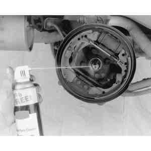
    Fig. 2: Evaporative spray brake cleaners should be used to clean brake components

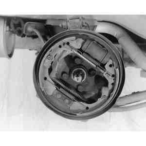
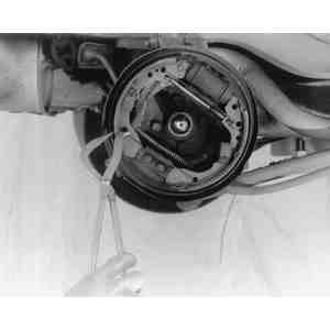
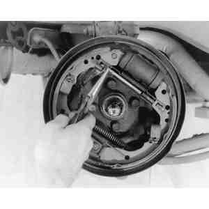
    Fig. 3: Note the positions of the various components before beginning disassembly. If necessary, you can refer to the brakes on the other side of the vehicle, but keep in mind that the two sides will be "reversed,'' like mirror images

  2. To ease removal of the leading shoe, and installation of the return spring later, insert an ordinary screwdriver into the gap between the quadrant of the automatic adjuster mechanism and twist it in the arrowed direction to release tension.

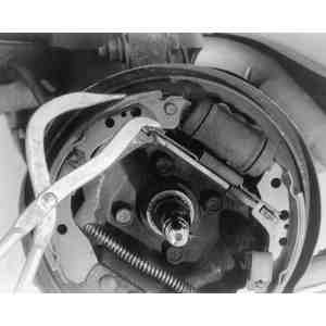
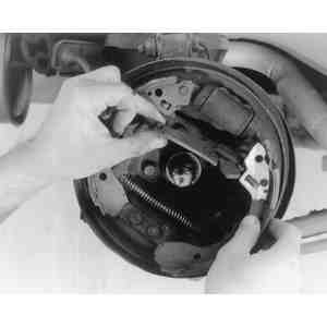
    Fig. 4: Release tension on the self-adjuster mechanism by inserting a screwdriver and moving the quadrant in the arrowed direction

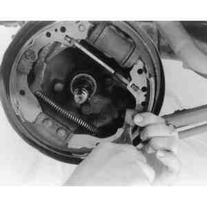
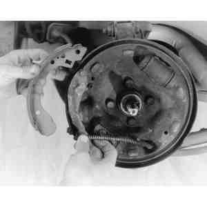
    Fig. 5: Remove the upper and lower return springs which bridge the leading and trailing shoes

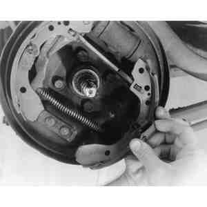
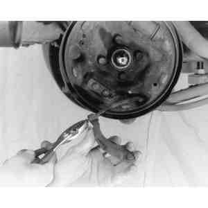
    Fig. 6: Brake pliers are specially designed for this task

    Fig. 7: Use needlenose pliers to twist . . .

    Fig. 8: . . . then disengage the clips and pins which secure the shoes to the backing plate

  3. Use brake pliers to remove the return springs. Then, use needle nose pliers to remove the holding pins and clips from the backing plate.
  4. Push the bottoms of the shoes outward in order to release them from the anchors and then unhook them at the wheel cylinder. Remove the leading shoe first.

    NOTE: Although the leading and trailing brake shoes can be removed separately, it may be easier to remove them as an assembly, with the self-adjuster and anti-rattle spring. In any event, they must be replaced in sets.

    Fig. 9: The anti-rattle spring attaches to the adjuster and the trailing shoe

    Fig. 10: The adjuster can be removed with the leading shoe

    Fig. 11: Separate the operating lever (connected to the parking brake cable) from the trailing shoe

    Fig. 12: If necessary, disengage the end of the parking brake cable from the operating lever

  5. Remove the anti-rattle spring and adjuster, if new shoes are to be installed. Unless the replacement trailing shoe comes with another operating lever, also remove the retainer which fastens the lever to the shoe, then separate the operating lever.
  6. The linings must be at least 0.04 in. (1mm) thick or conform to inspection standards in your state. Replace them regardless of the thickness if there are any signs of peeling or cracks. The brake drum should be turned if there is grooving or cracking. The limit on inner diameter is 7.9 in. (201mm).

    NOTE: Brake shoes should be replaced as a set on each wheel. Both rear wheels should be serviced if either side shows excessive wear.

    To install:

  7. Apply grease to the areas shown in the accompanying illustration by both types of arrows.

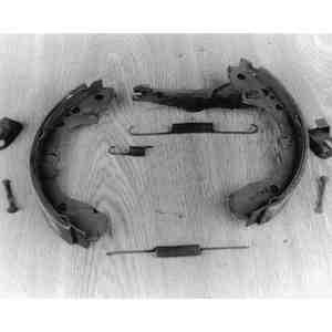
    Fig. 13: Disassembled brake shoes and related hardware

    Fig. 14: Grease the wheel cylinder and anchor pin (at the spots indicated by the thicker arrows), and the backing plate (at the spots indicated by the thinner arrows)

  8. If applicable, insert the operating lever pivot pin through the trailing shoe and secure with a new horseshoe clip.
  9. Connect the upper return spring to the trailing shoe assembly.

    WARNING
    Be careful not to get oil or grease on the lining surfaces.

  10. Position the trailing brake shoe against the wheel cylinder and anchor plate. Retain the trailing shoe with the holding pins and clips.
  11. Install the adjuster and anti-rattle spring to the trailing shoe.
  12. Connect the lower return spring to the trailing and leading brake shoes.
  13. Install the leading brake shoe onto the adjuster, then to the wheel cylinder and anchor plate.
  14. Install the remaining upper return spring.
  15. Repeat Steps 1–13 for the other side of the vehicle.
  16. Be sure to apply the brakes several times before the vehicle is driven; the shoe clearance will be adjusted automatically.

Previous Next