Previous Next

Master Cylinder

REMOVAL & INSTALLATION

  1. Remove the air cleaner for clearance if necessary.
  2. Detach the fluid level sensor connector and/or the pressure switch connector (bottom of the master cylinder on RX-7s).
  3. Place a rag under the hydraulic lines and loosen their fittings at the master cylinder. (If equipped with ABS, loosen, then disconnect the union fittings and washers. Discard the washers as they must be replaced with ones.) Position a container to collect any escaping brake fluid, then detach the hydraulic lines from the master cylinder.

    NOTE: On older 626 models which have a fluid reservoir located separately from the master cylinder, disconnect the lines which run between the two and plug them to prevent leakage.

    Fig. 1: Exploded view of master cylinder on vehicles equipped with ABS (929 shown, others similar)

  4. Unfasten the nuts which secure the master cylinder to the power brake unit.
  5. Withdraw the master cylinder assembly from the power brake unit. (If so equipped, remove the old gasket from the power brake unit.) On 1988–89 626s and MX-6s equipped with either a manual transaxle or ABS, and on all 929s, remove the clutch pipe mounting bracket from the power brake unit.

    NOTE: Be careful not to spill brake fluid on the painted surfaces of the car, as it makes an excellent paint remover.

    To install:

  6. On 1988–89 626s, MX-6s and 929s, install the clutch pipe mounting bracket if so equipped. If applicable, place a new gasket onto the brake power unit mounting studs. Position the master cylinder onto the mounting studs, then install and tighten the nuts.
  7. Connect the hydraulic brake lines to the master cylinder. On ABS equipped vehicles, install new washers and torque the fitting union bolts to 16–20 ft. lbs. (22–27 Nm).

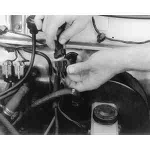
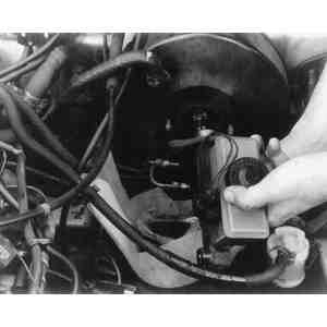
    Fig. 2: Disconnect the wire which runs to the fluid level sensor in the master cylinder

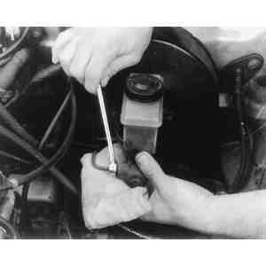
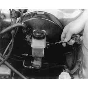
    Fig. 3: Loosen the hydraulic lines at the master cylinder while holding a rag beneath them

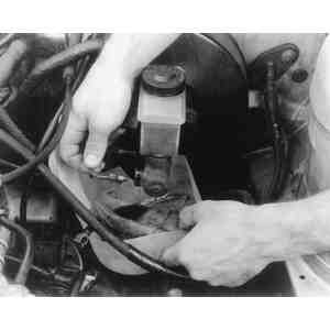
    Fig. 4: Disconnect the hydraulic lines and collect the brake fluid as it drains

    Fig. 5: Unfasten the nuts which secure the master cylinder to the power brake booster

    Fig. 6: Separate the master cylinder from the power brake booster

  8. Fasten the fluid level sensor and/or harness connectors.
  9. Fill the reservoir with clean brake fluid and bleed the system, as described later in this section.

Previous Next