CAUTION
On fuel injected models, fuel in the system remains under high pressure, even
when the engine is not running. Before disconnecting any fuel line, release
the pressure from the fuel system to reduce the possibility of injury or fire.
Never smoke when working around gasoline! Avoid all sources of sparks or ignition.
Gasoline vapors are EXTREMELY volatile!
| Fig. 1: Intake manifold assembly components — 2.2L
engine
|
- Disconnect the negative battery cable. Drain the cooling system.
- Remove the air cleaner assembly.
- Disconnect the accelerator cable. Tag and disconnect the necessary electrical
connectors and vacuum hoses.
- Disconnect the coolant hoses and fuel line.
- Remove the intake manifold mounting nuts and remove the intake manifold.
To install:
- Clean all gasket mating surfaces.
- Position a new intake manifold gasket on the cylinder head and install the
intake manifold.
- Install the intake manifold mounting nuts and tighten, in 2–3 steps,
to 14–19 ft. lbs. (19–25 Nm) on 2.2L engine or 11–14 ft.
lbs. (15–19 Nm) on 2.6L engine. Tighten the nuts at the center of the
manifold first and work towards the ends.
- Connect the fuel line and the coolant hoses.
- Connect the electrical connectors and vacuum hoses. Connect the accelerator
cable.
- Install the air cleaner assembly and connect the negative battery cable.
- Fill and bleed the cooling system. Run the engine and check for leaks.
| Fig. 2: Intake manifold assembly components — 2.6L
engine
|
- Relieve the fuel system pressure and disconnect the negative battery cable.
Drain the cooling system.
- Disconnect the air intake tube and ventilation hose. Remove the air pipe
and resonance chamber on 2.6L engine.
- Disconnect the accelerator cable and coolant hoses. Tag and disconnect the
electrical connectors to the solenoid valve, throttle sensor and idle switch.
- Remove the throttle body.
- Remove the upper intake manifold brackets.
- Tag and disconnect the vacuum hoses and PCV hose. Tag and disconnect the
intake air thermosensor connector and ground wire.
- Remove the injector harness bracket and remove the upper intake manifold.
- Tag and disconnect the vacuum hoses from the lower intake manifold. Disconnect
the fuel lines.
- Remove the fuel supply manifold and the injectors. Remove the injector harness
and bracket.
- Remove the pulsation damper and the intake manifold bracket. Remove the
attaching nuts and remove the lower intake manifold.
To install:
- Clean all gasket mating surfaces.
- Position a new intake manifold-to-cylinder head gasket and install the lower
intake manifold. Tighten the nuts to 14–19 ft. lbs. (19–25 Nm).
- Install the intake manifold bracket and pulsation damper. Install the injector
harness and bracket. Tighten the pulsation damper and injector harness bracket
bolts to 69–95 inch lbs. (7.8–11.0 Nm).
- Install the injectors and the fuel supply manifold. Tighten the fuel supply
manifold attaching bolts and tighten to 14–19 ft. lbs. (19–25
Nm).
- Connect the fuel lines. Connect the vacuum hoses to the lower intake manifold.
- Position a new gasket and install the upper intake manifold. Tighten the
attaching bolts/nuts to 14–19 ft. lbs. (19–25 Nm).
- Install the injector harness bracket. Connect the ground wire and air thermosensor
electrical connector. Connect the PCV hose and the vacuum hoses to the upper
intake manifold.
- Install the upper intake manifold brackets.
- Position a new gasket and install the throttle body. Tighten the mounting
nuts to 14–19 ft. lbs. (19–25 Nm).
- Connect the electrical connectors at the idle switch, throttle sensor and
solenoid valve.
- Connect the coolant hoses and the accelerator cable. On 2.6L engine, install
the air pipe and resonance chamber.
- Connect the ventilation hose and air intake hose. Connect the negative battery
cable.
- Fill and bleed the cooling system. Run the engine and check for leaks and
proper operation.
- Relieve the fuel system pressure and disconnect the negative battery cable.
Drain the cooling system.
- Remove the air intake tube from the throttle body. Disconnect the accelerator
cable.
- Disconnect the throttle sensor connector and the coolant hoses. Remove the
throttle body.
- Tag and disconnect the vacuum hoses. Remove the bypass air control valve
and the intake air pipe.
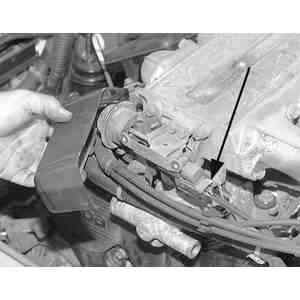
| Fig. 3: Remove the front cover from the dynamic chamber
and discontinue the electrical connector to the shutter valve actuator
before removing the dynamic chamber
|
- Remove the extension manifolds. Remove the upper intake plenum with the
shutter valve actuator.
- Remove the fuel supply manifold and the injectors. Disconnect the coolant
hoses.
- Loosen the lower intake manifold nuts, in sequence, in 2 steps and remove
the lower intake manifold.
To install:
- Clean all gasket mating surfaces.
- Position new lower intake manifold-to-cylinder head gaskets and install
the lower intake manifold.
| Fig. 4: Intake manifold tightening sequence
|
- Install the intake manifold washers with the white paint mark upward. Install
the nuts and tighten, in sequence, in 2 steps to a maximum torque of 14–19
ft. lbs. (19–25 Nm).
- Install the injectors and the fuel supply manifold. Tighten the attaching
bolts to 14–19 ft. lbs. (19–25 Nm).
- Connect the coolant hoses.
- Install a new O-ring on the lower intake manifold and install the upper
intake plenum. Apply clean engine oil to new O-rings and install on the extension
manifolds. Position new gaskets and install the extension manifolds. Tighten
the attaching nuts to 14–19 ft. lbs. (19–25 Nm).
- Position a new gasket and install the intake air pipe. Install the bypass
air control valve. Tighten the attaching bolts/nuts to 14–19 ft. lbs.
(19–25 Nm).
- Position a new gasket and install the throttle body. Tighten the attaching
nuts to 14–19 ft. lbs. (19–25 Nm).
- Connect the coolant and vacuum hoses. Connect the throttle sensor connector
and accelerator cable.
- Adjust the accelerator cable deflection to 0.039–0.118 inch (1–3mm).
- Connect the air intake tube and the negative battery cable.
- Fill and bleed the cooling system. Run the engine and check for leaks and
proper operation.
- Disconnect the negative battery cable and relieve the fuel system pressure.
- Remove the air cleaner air intake duct from the throttle body.
- Remove the snow/ice shield and disconnect the throttle cable and bracket
assembly.
- Tag and disconnect the vacuum hoses from the fittings on the upper intake
manifold.
- Tag and disconnect the electrical connectors at the throttle body, upper
intake manifold, lower intake manifold and injectors.
- Disconnect the fuel lines from the fuel supply manifold.
- Remove the ignition coil and bracket assembly.
- Remove the mounting nuts and remove the upper intake manifold.
- Remove the rocker arm covers.
- Remove the intake manifold attaching bolts and nuts. Tap the manifold lightly
with a plastic mallet to break the gasket seal and remove the manifold.
To install:
- Clean all gasket mating surfaces.
- Apply silicone sealer to the block and cylinder head mating surfaces at
the 4 corners of the lifter valley opening. Install the intake manifold gaskets
and again apply sealer to the same locations.
| Fig. 5: Intake manifold tightening sequence
|
- Position the intake manifold on the 2 guide studs and install the nuts and
bolts hand tight. Tighten the bolts, in sequence, in 4 steps, first to 3–6
ft. lbs. (4–8 Nm), then to 6–11 ft. lbs. (8–15 Nm), then
to 11–15 ft. lbs. (15–21 Nm) and finally to 15–18 ft. lbs.
(21–25 Nm).
- Apply silicone sealer to the 4 locations where the intake manifold and the
cylinder heads meet. Install the rocker arm covers with new gaskets and tighten
evenly to 3–5 ft. lbs. (4–7 Nm). Wait 2 minutes and tighten the
bolts again to the same specification.
- Install the upper intake manifold and tighten the nuts to 15–18 ft.
lbs. (20–25 Nm).
- Install the ignition coil and bracket assembly. Connect the fuel lines to
the fuel supply manifold.
- Connect the electrical connectors at the throttle body, upper intake manifold,
lower intake manifold and injectors.
- Connect the vacuum hoses to the fittings on the upper intake manifold.
- Install the throttle cable and bracket assembly and the snow/ice shield
to the throttle body.
- Connect the air cleaner air intake duct to the throttle body.
- Connect the negative battery cable. Fill and bleed the cooling system. Run
the engine and check for leaks.