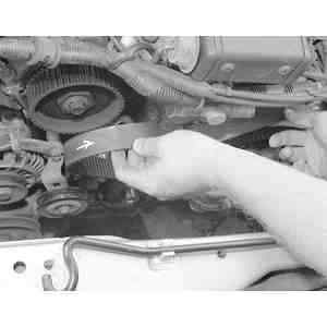
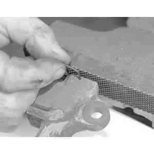
| Fig. 1: Inspect the timing belt for damage
|
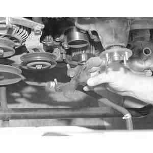
| Fig. 2: Timing belt sprocket matching marks
|
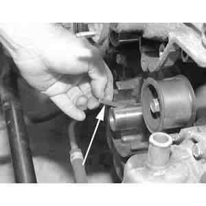
| Fig. 3: Removing the timing belt sprocket lock bolt
|
| Fig. 4: If installing the old timing belt, be sure
to install it in the same rotational direction as before removal
|
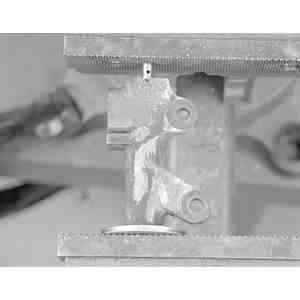
| Fig. 5: Positioning the timing belt tensioner
|
| Fig. 6: Tighten the timing belt tensioner lock bolt
|
| Fig. 7: Timing belt deflection checking point
|
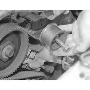
| Fig. 8: Remove the upper idler pulley
|
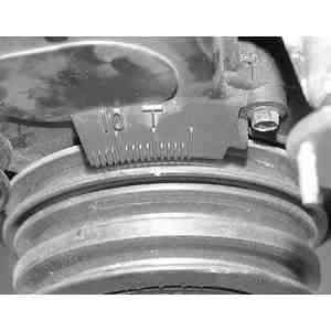
| Fig. 9: Location of the timing marks on the timing belt
cover
|
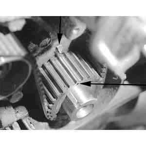
| Fig. 10: Before removing the timing belt, line up the
timing marks on the crankshaft sprocket and the engine block . . .
|
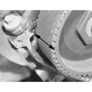
| Fig. 11: . . . the right side camshaft sprocket and the
mark on the cylinder head . . .
|
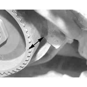
| Fig. 12: . . . and the left side camshaft sprocket and
the cylinder head
|
| Fig. 13: Mark the direction of rotation on the timing
belt if installing the same belt
|
| Fig. 14: Rmove the timing belt
|
| Fig. 15: Remove the timing belt tensioner from the front
of the engine
|
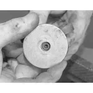
| Fig. 16: Remove the cranshaft sprocket by pulling straight
off of the crankshaft
|
| Fig. 17: After removing the crankshaft sprocket, remove
the woodruff ke. Be careful not to lose this
|
To install:
| Fig. 18: Place the washer on the tensioner allowing
the plug on the tensioner to fit through the hole in the washer
|
| Fig. 19: Mount the tensioner assembly and washer
in the bench vise as shown
|
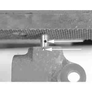
| Fig. 20: When compressing the tensioner and plunger,
be sure to line up the holes of the plunger to the hole in the tensioner
body
|
| Fig. 21: Once the plunger and tensioner holes are
aligned . . .
|
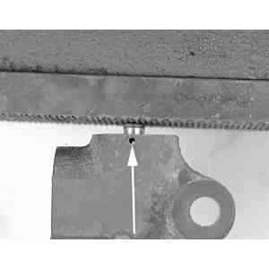
| Fig. 22: . . . place a small hex key into the holes
to keep the plunger compressed
|
NOTE: Do not press the tensioner rod more than 2200 lbs. (9800N).