Previous Next

TESTING

Navajo
  1. With the engine running at idle, use a DVOM to verify there is at least 10.5 volts between terminals A and B of the MAF sensor connector. This indicates the power input to the sensor is correct. Then, measure the voltage between MAF sensor connector terminals C and D. If the reading is approximately 0.34–1.96 volts, the sensor is functioning properly.

    Fig. 1: MAF sensor wire harness connections

Pick-up and MPV Models
MAF SENSOR
  1. Remove the rubber boot from the Mass Air Flow (MAF) sensor wiring connector.
  2. Using a voltmeter, measure the terminal voltages. Refer to the specifications chart.

    Fig. 2: Using a voltmeter to measure terminal voltages

    Fig. 3: MAF sensor voltage specifications chart

  3. If not as specified, inspect the wiring harness for an open or short circuit. If the wiring is okay, check the burn off operation as follows:
    1. Disconnect the negative battery cable for 20 seconds and reconnect it.
    2. Start the engine and allow it to warm up to operating temperature.
    3. Remove the rubber boot from the Mass Air Flow (MAF) sensor wiring connector.
    4. Run the engine for more than 5 seconds at approximately 2000 rpm in neutral.
    5. Turn the ignition switch OFF and check the voltage at the MAF sensor terminal wire (G/O) and terminal 2H of the powertrain control module. There should be 0 volts just after the ignition switch is turned OFF, then approximately 8 volts battery positive voltage momentarily 2–5 seconds after turning the ignition switch OFF.
  4. If not as specified, replace the MAF sensor.
VOLUME AIR FLOW SENSOR

NOTE: Testing of the volume air flow sensor also includes testing of the integral intake air temperature sensor.

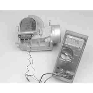
Fig. 4: Checking the resistance of the volume airflow sensor with the shutter closed

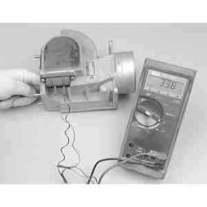
Fig. 5: Checking the resistance of the volume airflow sensor while moving the shutter

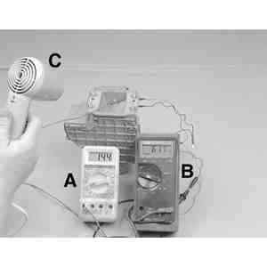
Fig. 6: Using a voltmeter with a temperature probe (A), an ohmmeter (B) and a hairdryer (C), measure the resistance fluctuation of the integral intake air temperature sensor

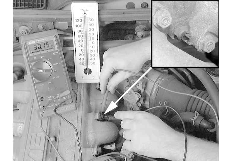
Fig. 7: Checking the resistance of the intake air temp sensor

  1. Remove the volume air flow sensor from the vehicle.
  2. Inspect the volume air flow sensor for cracks or any other signs of damage.
  3. Check that the sensor shutter plate opens and closes smoothly.

    Fig. 8: Volume air flow sensor terminal identifications

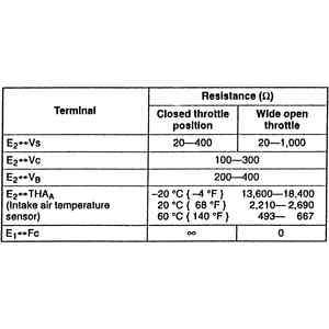
    Fig. 9: Resistance specifications for the volume air flow sensor

  4. Using an ohmmeter, open and close the sensor shutter plate while checking the resistance between the terminals.
  5. Using a voltmeter with a temperature probe, an ohmmeter and a hairdryer for temperature variation, measure the resistance fluctuation of the integral intake air temperature sensor.
  6. If the resistance does not measure within specifications, replace the volume air flow sensor.

Previous Next