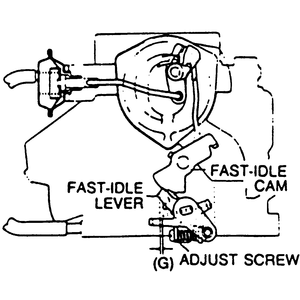
- Set the fast idle cam so that the fast idle lever rests on the second step
of the cam.
- Adjust the clearance between the air horn wall and the lower edge of the
throttle plates, by turning the fast idle adjusting screw. Clearance should
be 0.0331–0.0409 inch (0.84–1.04mm). Make sure that the choke
valve clearance hasn't changed.
| Fig. 1: Fast idle cam adjustment
|
NOTE: Before making the adjustment, the carburetor should be
at 73°F (23°C) for at least 1 hour.
- With the carburetor off the engine, invert it and check the opening between
the throttle plate and the air horn wall. The clearance should be 0.0279 inch
(0.71mm) if equipped with manual transmission; 0.0315 inch (0.80mm) if equipped
with automatic transmission.
- If not, adjust the opening by turning the fast idle adjustment screw.
Make sure the ignition timing, spark plugs, and carburetor float level are
all in normal operating condition. Turn off all lights and other unnecessary
electrical loads.
- Connect a tachometer to the engine.
- Start the engine and allow it to reach normal operating temperature. Make
sure the choke valve has fully opened.
- Check the idle speed. If necessary, adjust it to specification by turning
the throttle adjusting screw. The idle speed should be 800–850 rpm with
manual transmission in neutral or automatic transmission in P.
- Start the engine and allow it to reach normal operating temperature. Let
the engine run at idle.
- Connect a dwellmeter (90°, 4-cylinder) to the air/fuel check connector
(Br/Y).
- Check the idle mixture at the specified idle speed. The idle mixture should
be 20–70°. If the idle mixture is not as specified, adjust as follows:
- Remove the carburetor and knock out the spring pin. Install the carburetor.
- Install the air cleaner and make sure the idle compensator is closed.
Make sure all vacuum hoses are properly connected.
- Connect a tachometer to the engine.
- Warm up the engine and run it at idle. Make sure the idle speed is correct.
- Reconnect the dwell meter to the air/fuel check connector.
- Adjust the idle mixture to 27–45°by turning the mixture adjust
screw.
- Tap in the spring pin.
- Start the engine and allow it to reach normal operating temperature. Let
the engine run at idle.
- Connect a dwellmeter (90°, 4-cylinder) to the jet mixture solenoid
valve connector (Y/G) wire. The check connector is located near the No. 3
ACV and reed valve case assembly.
- Check the idle mixture at the specified idle speed. The idle mixture should
be 27–45°. If the idle mixture is not as specified, check the oxygen
sensor, feedback control unit and the wiring between the sensor and control
unit.
- If the oxygen sensor, feedback control unit and wiring are okay, adjust
the idle mixture as follows:
- Remove the carburetor and mount it in a vise with the mixture adjust
screws facing up. Protect the gasket surface from the vise jaws.
- Drill a 0.079 inch (2mm) pilot hole in the casting toward the mixture
adjust screw, then redrill the hole to 0.118 inch (3mm).
- Insert a blunt punch into the hole and drive out the antitamper plug.
Reinstall the carburetor.
- Connect a tachometer to the engine. Start the engine and allow it to
reach normal operating temperature. Let the engine run at idle. Make sure
the idle speed is correct.
- Reconnect the dwell meter to the jet mixture solenoid valve connector.
Adjust the idle mixture to 36°± 9°by turning the mixture
adjust screw.
- Press in a new antitamper plug.
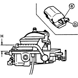
- Remove the air horn from the carburetor.
| Fig. 2: Adjusting the float level with the air horn
turned upside down
|
- Turn the air horn upside down on a level surface. Allow the float to hang
under its own weight.
- Measure the clearance between the float and the air horn gasket surface.
The gap should be 0.4567–0.4960 inch (11.6–12.6mm) for vehicles
with manual transmission; 0.4212–0.4606 inch (10.7–11.7mm) for
vehicles with automatic transmission. If not, bend the float seat lip to obtain
the correct gap.
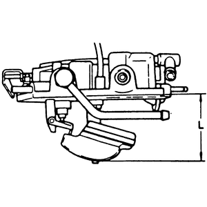
| Fig. 3: Adjusting the float level with the air horn
right side up and the float hanging under its own weight
|
- Turn the air horn right side up and allow the float to hang under its own
weight.
- Measure the gap between the BOTTOM of the float and the air horn gasket
surface. The gap should be 1.811–1.850 inch (46.0–47.0mm). If
not, bend the float stopper until it is.
- Remove air horn from carburetor main body.
- Remove air horn gasket and invert air horn.
- Using a gauge measure the distance from bottom of float to air horn surface.
The distance should be 0.787 inch ± 0.0394 inch (20mm ± 1mm).
If distance is not within specification, the shim under the needle and seat
must be changed. A shim pack is available which has three shims: 0.008 inch
(0.2mm), 0.012 inch (0.3mm), or 0.021 inch (0.5mm). Adding or removing one
shim will change the float level three times its thickness.
- Check the cable deflection at the carburetor. Deflection should be 0.0394–0.1181
inch (1.0–3.0mm) . If not, adjust it by turning the adjusting nut at
the bracket near the carburetor.
- Depress the accelerator pedal to the floor. The throttle plates should be
vertical. If not, adjust their position by turning the adjusting nut on the
accelerator pedal bracket.
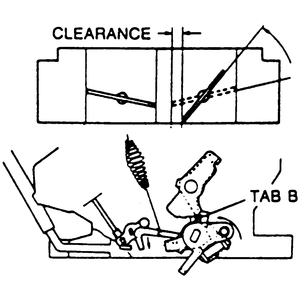
The clearance between the primary throttle valve and the air horn wall, when
the secondary throttle valve just starts to open should be 0.2894–0.3249
inch (7.35–8.25mm). If not, bend the tab.
| Fig. 4: Adjusting the secondary throttle valve clearance
|
Three choke related adjustments are performed on these units.
- Disconnect the vacuum line from the choke diaphragm unit.
| Fig. 5: Adjusting the choke diaphragm
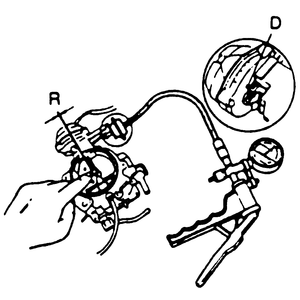
|
- Using a vacuum pump, apply 15.7 inch Hg to the diaphragm.
- Using light finger pressure, close the choke valve. Check the clearance
at the upper edge of the choke valve. Clearance should be 0.067–0.085
inch (1.70–2.16mm).
- If not, bend the tab on the choke lever to adjust it.
| Fig. 6: Adjusting the choke valve clearance
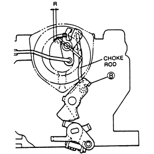
|
- Position the fast idle lever on the second step of the fast idle cam.
- The leading edge of the choke valve should be 0.024–0.045 inch (0.60–1.14mm)
from fully closed. If not, bend either the tab on the cam or the choke rod
to adjust. The tab will give smaller adjustment increments.
- Open the primary throttle valve all the way and hold it in this position.
| Fig. 7: Adjusting the choke unloader system
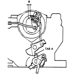
|
- The leading edge of the choke valve should be 0.110–0.143 inch (2.80–3.62mm)
from fully closed. If not, bend the tab on the throttle lever.
- The idle switch adjustment is not necessary unless it has been replaced
or tampered with.
- Start the engine and allow it to reach normal operating temperature. Stop
the engine and connect a suitable tachometer.
- Connect a voltmeter to the idle switch terminal (LgR).
- Start the engine and increase the speed to above 2000 rpm and decelerate
gradually.
- Take a reading on the voltmeter. At idle, there should be approximately
12 volts and above 100–1200 rpm it should be below 1.5 volts.
- If the readings do not agree with these specifications, turn the adjusting
screw to obtain the correct reading.

