NOTE: See Section 7 for servicing 4WD models.
- Raise and safely support the vehicle. Remove the wheel and tire assembly.
- Remove the brake caliper and support it with mechanics wire. Do not let
the caliper hang by the brake hose.
- Remove the grease cap, cotter pin, retainer, adjusting nut and washer. Discard
the cotter pin.
- Remove the outer bearing and pull the hub and rotor off the spindle. Remove
the grease seal using a seal removal tool. Discard the grease seal.
- Remove the inner bearing from the hub. Remove all traces of old lubricant
from the bearings, hub and spindle with solvent and dry thoroughly.
- Inspect the bearings and bearing races for scratches, pits or cracks. If
the bearings and/or races are worn or damaged, remove the races with a brass
drift.
To install:
- If the bearing races were removed, install new races in the hub with suitable
installation tools. Make sure the races are properly seated.
- Using a bearing packer, pack the bearings with high-temperature wheel bearing
grease. If a packer is not available, work as much grease as possible between
the rollers and cages by hand.
- Place a small amount of grease within the hub and grease the races. Install
the inner bearing. Install a new wheel seal using a seal installer. Apply
grease to the lips of the seal.
- Install the hub and rotor assembly on the spindle. Install the outer bearing,
washer and adjusting nut. Adjust the bearings.
- Install the retainer, a new cotter pin and the grease cap.
- Install the caliper and the wheel and tire assembly. Lower the vehicle.
- Before driving the vehicle, pump the brake pedal several times to restore
normal brake travel.
| Fig. 1: Remove the dust cap from the wheel hub, using
pliers, if necessary
|
| Fig. 2: Installing the dust cap onto the wheel hub using
a hammer and a 2 3/8 inch socket
|
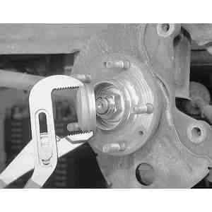
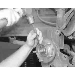
| Fig. 3: If the wheel hub retaining nut was staked previously,
open it up using a hammer and a punch or drift
|
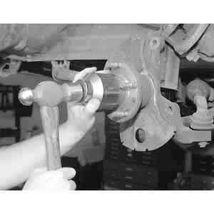
| Fig. 4: Using a 34mm deep well socket, remove the wheel
hub retaining nut
|
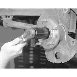
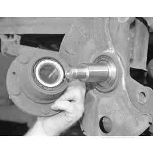
| Fig. 5: Remove the whel hub/bearing assembly by sliding
straight off of the spindle
|
- Raise and safely support the vehicle.
- Remove the wheel assembly.
- Remove the hub dust cap.
- Remove the locknut.
- Remove the brake caliper.
- Remove the disc plate.
- Remove the hub assembly.
To install:
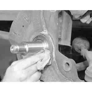
| Fig. 6: Be sure to clean the spindle area of any
debris using a towel
|
| Fig. 7: After installing the wheel hub/bearing assembly
and retaining nut, use a torque wrench to tighten the nut
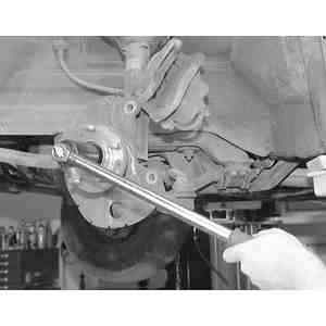
|
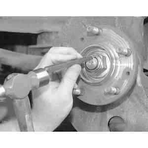
| Fig. 8: Using a hammer and a punch or drift, stake
the hub/bearing retaining nut onto the spindle
|
- Install the hub assembly.
- Install the disc plate.
- Install the brake caliper, torque the mounting bolts to 66–79 ft.
lbs. (89–107 Nm).
- Install the locknut, torque to 131–173 ft. lbs. (117–235 Nm).
- Using a hammer and a punch or drift, stake the hub/bearing retaining nut
onto the spindle.
- Install the hub dust cap.
- Install the wheel assembly.
- Lower the vehicle.
| Fig. 9: Front hub and related components, exploded view — 4WD
|
- Raise and safely support the vehicle.
- Remove the wheel assembly.
- Remove the locknut.
- Remove the brake caliper.
- Remove the disc plate retaining screw(s).
- Disconnect the tie-rod end from the knuckle.
- Disconnect the lower ball joint.
- Remove the disc plate.
- Remove the ball joint mounting nuts and bolts.
- Remove the knuckle, wheel hub and dustplate as an assembly.
- Remove the wheel hub/bearing assembly from the knuckle.
To install:
- Install wheel hub/bearing assembly to the knuckle.
- Install the knuckle assembly. Torque the strut mounting nut to 69–86
ft. lbs. (94–116 Nm).
- Install the ball joint mounting nuts and bolts. Torque the upper mounting
bolts to 76–101 ft. lbs. (102–137 Nm). Torque the through-bolt
nut to 95–106 ft. lbs. (128–171 Nm).
- Replace the disc plate.
- Install ball joint to the knuckle assembly. Torque the ball joint nut to
116–137 ft. lbs. (157–186 Nm).
- Connect the tie-rod end, torque the nut to 44–57 ft. lbs. (59–78
Nm).
- Install the brake caliper, torque the mounting bolts to 66–79 ft.
lbs. (89–107 Nm).
- Install the disc plate retaining nut.
- Install the locknut, torque to 174–231 ft. lbs. (236–313 Nm).
- Install the wheel assembly.
- Lower the vehicle.
NOTE: See Section 7 for servicing 4WD models.
- Raise and support the vehicle safely. Remove the tire and wheel assembly
from the hub and rotor.
- Remove the caliper from its mounting and position it to the side with mechanics
wire in order to prevent damage to the brake line hose.
- Remove the grease cap from the hub. Remove the cotter pin, retainer, adjusting
nut and flatwasher from the spindle.
- Remove the outer bearing cone and roller assembly from the hub. Remove the
hub and rotor from the spindle.
- Using seal removal tool 1175–AC or equivalent remove and discard the
grease seal. Remove the inner bearing cone and roller assembly from the hub.
- Clean the inner and outer bearing assemblies in solvent. Inspect the bearings
and the cones for wear and damage. Replace defective parts, as required.
- If the cups are worn or damaged, remove them with front hub remover tool
T81P–1104–C and tool T77F–1102–A or equivalent.
- Wipe the old grease from the spindle. Check the spindle for excessive wear
or damage. Replace defective parts, as required.
To install:
- If the inner and outer cups were removed, use bearing driver handle tool
T80–4000–W or equivalent and replace the cups. Be sure to seat
the cups properly in the hub.
- Use a bearing packer tool and properly repack the wheel bearings with the
proper grade and type grease. If a bearing packer is not available work as
much of the grease as possible between the rollers and cages. Also, grease
the cone surfaces.
- Position the inner bearing cone and roller assembly in the inner cup. A
light film of grease should be included between the lips of the new grease
retainer (seal).
- Install the retainer using the proper installer tool. Be sure that the retainer
is properly seated.
- Install the hub and rotor assembly onto the spindle. Keep the hub centered
on the spindle to prevent damage to the spindle and the retainer.
- Install the outer bearing cone and roller assembly and flatwasher on the
spindle. Install the adjusting nut. Adjust the wheel bearings.
- Install the retainer, a new cotter pin and the grease cap. Install the caliper.
- Lower the vehicle and tighten the lug nuts to 100 ft. lbs. Before driving
the vehicle pump the brake pedal several times to restore normal brake pedal
travel.
CAUTION
Tighten the wheel lug nuts to specification after about 500 miles of driving.
Failure to do this could result in the wheel coming off while the vehicle
is in motion possibly causing loss of vehicle control or collision.