- Raise the vehicle and support on jackstands.
- Remove the wheel and tire assembly.
- Remove the caliper.
- Remove hub locks, wheel bearings, and locknuts.
- Remove the hub and rotor. Remove the outer wheel bearing cone.
- Remove the grease seal from the rotor with seal remover tool 1175–AC
and slide hammer 750T–100–A or equivalent. Discard seal and replace
with a new one upon assembly.
- Remove the inner wheel bearing.
- Remove the inner and outer bearing cups from the rotor with a bearing cup
puller.
- Remove the nuts retaining the spindle to the steering knuckle. Tap the spindle
with a plastic or rawhide hammer to jar the spindle from the knuckle. Remove
the splash shield.
- On the left side of the vehicle remove the shaft and joint assembly by pulling
the assembly out of the carrier.
- On the right side of the carrier, remove and discard the keystone clamp
from the shaft and joint assembly and the stub shaft. Slide the rubber boot
onto the stub shaft and pull the shaft and joint assembly from the splines
of the stub shaft.
- Place the spindle in a vise on the second step of the spindle. Wrap a shop
towel around the spindle or use a brass-jawed vise to protect the spindle.
- Remove the oil seal and needle bearing from the spindle with slide hammer
T50T–100–A and seal remover tool 1175–A–C or equivalent.
- If required, remove the seal from the shaft, by driving off with a hammer.
- If the tie rod has not been removed, then remove cotter pin from the tie
rod nut and then remove nut. Tap on the tie rod stud to free it from the steering
arm.
- Remove the upper ball joint cotter pin and nut. Loosen the lower ball joint
nut to the end of the stud.
- Strike the inside of the spindle near the upper and lower ball joints to
break the spindle loose from the ball joint studs.
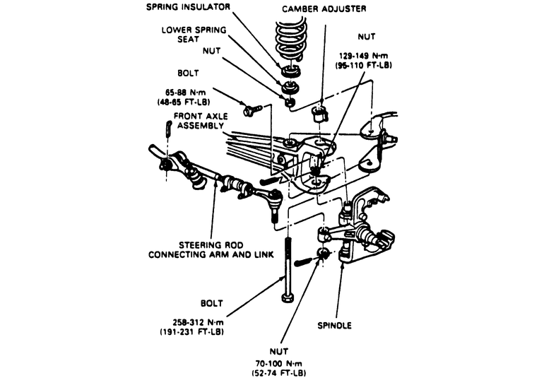
- Remove the camber adjuster sleeve. If required, use pitman arm puller, T64P–3590–F
or equivalent to remove the adjuster out of the spindle. Remove the lower
ball joint nut.
- Place knuckle in vise and remove snapring from bottom ball joint socket
if so equipped.
- Assemble the C-frame, T74P–4635–C, forcing screw, D79T–3010–AE
and ball joint remover T83T–3050–A or equivalent on the lower
ball joint.
- Turn forcing screw clockwise until the lower ball joint is removed from
the steering knuckle.
- Repeat Steps 20 and 21 for the upper ball joint.
NOTE: Always remove lower ball joint first.
To install:
- Clean the steering knuckle bore and insert lower ball joint in knuckle as
straight as possible. The lower ball joint doesn't have a cotter pin hole
in the stud.
- Assemble the C-frame, T74P–4635–C, forcing screw, D790T–3010–AE,
ball joint installer, T83T–3050–A and receiver cup T80T–3010–A3
or equivalent tools, to install the lower ball joint.
- Turn the forcing screw clockwise until the lower ball joint is firmly seated.
Install the snapring on the lower ball joint.
NOTE: If the ball joint cannot be installed to the proper
depth, realignment of the receiver cup and ball joint installer will be
necessary.
- Repeat Steps 24 and 25 for the upper ball joint.
- Install the camber adjuster into the support arm. Position the slot in its
original position.
CAUTION
The following torque sequence must be followed exactly when securing the
spindle. Excessive spindle turning effort may result in reduced steering
returnability if this procedure is not followed.
- Install a new nut on the bottom of the ball joint stud and torque to 90
ft. lbs. (minimum). Tighten to align the nut to the next slot in the nut with
the hole in the ball joint stud. Install a new cotter pin.
- Install the snapring on the upper ball joint stud. Install the upper ball
joint pinch bolt and torque the nut to 48–65 ft. lbs.
NOTE: The camber adjuster will seat itself into the knuckle
at a predetermined position during the tightening sequence. Do not attempt
to adjust this position.
- Clean all dirt and grease from the spindle bearing bore. Bearing bores must
be free from nicks and burrs.
- Place the bearing in the fore with the manufacturer's identification facing
outward. Drive the bearing into the bore using spindle replacer, T80T–4000S
and driver handle T80T–4000–W or equivalent.
- Install the grease seal in the bearing bore with the lip side of the seal
facing towards the tool. Drive the seal in the bore with spindle bearing replacer,
T83T–3123–A and driver handle T80–4000–W or equivalent.
Coat the bearing seal lip with Lubriplate® .
- If removed, install a new shaft seal. Place the shaft in a press, and install
the seal with spindle/axle seal installer, T83T–3132–A, or equivalent.
- On the right side of the carrier, install the rubber boot and new keystone
clamps on the stub slip yoke.
NOTE: This axle does not have a blind spline. Therefore,
special attention should be made to assure that the yoke ears are in line
during assembly.
- Slide the boot over the assembly and crimp the keystone clamp using keystone
clamp pliers, T63P–9171–A or equivalent.
- On the left side of the carrier slide the shaft and joint assembly through
the knuckle and engage the splines on the shaft in the carrier.
- Install the splash shield and spindle onto the steering knuckle. Install
and tighten the spindle nuts to 40–50 ft. lbs.
- Drive the bearing cups into the rotor using bearing cup replacer T73T–4222–B
and driver handle, T80T–4000–W or equivalent.
- Pack the inner and outer wheel bearings and the lip of the oil seal with
Multi–Purpose Long-Life Lubricant, C1AZ–19590–B or equivalent.
- Place the inner wheel bearing in the inner cup. Drive the grease seal into
the bore with hub seal replacer, T80T–4000–T and driver handle,
T80T–4000–W or equivalent. Coat the bearing seal lip with multipurpose
long life lubricant, C1AZ–19590–B or equivalent.
- Install the rotor on the spindle. Install the outer wheel bearing into cup.
NOTE: Verify that the grease seal lip totally encircles
the spindle.
- Install the wheel bearing, locknut, thrust bearing, snapring, and locking
hubs.