- Raise and safely support the vehicle. Remove the wheel and tire assembly.
- Support the lower control arm with a jack.
- Remove the cotter pin and nut from the lower ball joint stud. Separate the
ball joint from the knuckle using tool 49 0727 575 or equivalent.
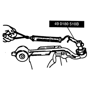
- Install tool 49 0180 510B or equivalent to the ball joint stud and attach
a suitable pull scale to the stud.
- After rocking the ball joint stud back and forth 3–4 times, measure
the pull scale reading while the ball joint stud is rotating. The pull scale
reading should be 4.4–7.7 lbs.
- If the pull scale reading is not as specified, replace the lower ball joint.
Defective ball joints are determined by checking the rotational torque with
a special preload attachment and spring scale.
- Remove the lower control arm from the vehicle.
- Inspect the control arm for damage and the boots for cracks. Replace them
if necessary.
- Inspect the ball joint for looseness and replace, if necessary.
- Shake the ball joint stud at least 5 times.
| Fig. 1: Inspecting the rotational torque of the ball
joint using a spring scale

|
- Install tool 49 0180 510B or equivalent to the ball joint stud and attach
a suitable pull scale to the stud.
- After shaking the ball joint stud back and forth 5 times, measure the rotational
torque while the ball joint stud is rotating. The rotational torque should
be 18–30 inch lbs. (2–3 Nm). The pull scale reading should be
4.4–7.7 lbs.
- If the reading is not as specified, replace the lower ball joint (4WD) or
control arm assembly (rear wheel drive).
- Raise the vehicle and position a jackstand under the I-beam axle beneath
the coil spring. Check and adjust the front wheel bearings.
- Have a helper grasp the upper edge of the tire and move the wheel assembly
in and out.
- While the wheel is being moved, observe the lower spindle arm and the lower
part of the axle jaw.
- One thirty-second inch (0.8mm) or greater movement between the lower part
of the axle jaw and the lower spindle arm indicates that the lower ball joint
must be replaced.

