Previous Next

REMOVAL & INSTALLATION

Pickup
  1. Raise and safely support the vehicle. Remove the wheel and tire assembly.
  2. Support the lower control arm with a jack.
  3. Remove the cotter pin and nut from the lower ball joint stud. Separate the ball joint from the knuckle using tool 49 0727 575 or equivalent.
  4. Remove the bolt, washer and nut attaching the shock absorber to the lower control arm.
  5. Remove the torsion bar, anchor arm and torque plate assembly.
  6. Remove the bolt(s) and nut(s) attaching the lower control arm to the frame.
  7. On 2WD vehicles, remove the bolts attaching the tension rod to the lower control arm.
  8. Remove the bolts, bushings, retainers, spacer and nuts connecting the stabilizer bar to the lower control arm.
  9. Remove the lower control arm from the vehicle. Remove the lower ball joint, if necessary.

    To install:

  10. Position the lower control arm to the frame and install the attaching bolt(s) and nut(s), but do not tighten at this time.
  11. Install the torsion bar, anchor arm and torque plate assembly.
  12. On 2WD vehicles, install the tension rod bolt and tighten to 69–86 ft. lbs. (93–117 Nm).
  13. Attach the stabilizer bar to the control arm with the bolts, bushings, retainers, spacer and nuts. Tighten the nuts so 0.73 in. (18.5mm) of thread is exposed at the end of the bolt.
  14. Install the shock absorber to the lower control arm and loosely tighten the mounting bolt and nut.
  15. Install the wheel and tire assembly and lower the vehicle.
  16. With the vehicle unladen, tighten the lower control arm-to-frame bolt and nut on 2WD vehicles and the front side lower control arm-to-frame bolt and nut on 4WD vehicles to 87–116 ft. lbs. (118–157 Nm). Tighten the rear side lower control arm-to-frame bolt and nut on 4WD vehicles to 116–145 ft. lbs. (157–196 Nm).
  17. With the vehicle unladen, tighten the shock absorber-to-lower control arm bolt and nut to 41–59 ft. lbs. (55–80 Nm).
  18. Check vehicle ride height as follows:
    1. Check the front and rear tire pressures and bring to specification.
    2. Measure the distance from the center of each front wheel to the fender brim. The difference must not be greater than 0.39 in. (10mm).
    3. If the difference is not as specified, turn the necessary torsion spring anchor bolt to adjust.
  19. Check the front end alignment.
MPV
REAR WHEEL DRIVE

Fig. 1: Front lower control arm assembly

  1. Raise and safely support the vehicle. Remove the wheel and tire assembly.
  2. Remove the brake caliper and support it aside with mechanics wire, do not let it hang by the brake hose.

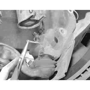
    Fig. 2: Remove and discard the lower ball joint stud cotter pin

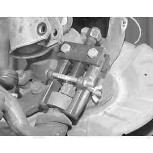
    Fig. 3: Using a ball joint separator tool, separate the steering knuckle from the lower ball joint

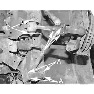
    Fig. 4: After separating the ball joint from the steering knuckle and sway bar link from the lower control arm, remove the 3 compression rod-to-control arm bolts (B), control arm bushing nut and through bolt (C) and 4 tailing arm-to-frame rail bolts (A)

  3. Remove the nuts, bolts, spacer, washers and bushings and remove the compression rod from the lower control arm and chassis and disconnect the stabilizer bar from the lower control arm.
  4. Remove the cotter pin and nut and, using tool 49 0118 850C or equivalent, separate the tie rod end from the knuckle.
  5. Remove the bolts and nuts and disconnect the strut from the knuckle.
  6. Remove the cotter pin and nut from the lower ball joint stud. Using tool 49 0727 575 or equivalent, separate the lower ball joint from the knuckle.
  7. Remove the mounting bolt and nut and remove the lower control arm from the vehicle.

    To install:

  8. Position the lower control arm to the chassis and install the bolt and nut, but do not tighten at this time.
  9. Install the knuckle to the lower control arm. Tighten the lower ball joint stud nut to 87–116 ft. lbs. (118–157 Nm) and install a new cotter pin.
  10. Connect the strut to the knuckle and tighten the attaching bolts and nuts to 69–86 ft. lbs. (93–117 Nm).
  11. Connect the tie rod end to the knuckle. Tighten the tie rod end stud nut to 43–58 ft. lbs. (59–78 Nm) and install a new cotter pin.
  12. Install the compression rod to the lower control arm and chassis. Tighten the compression rod-to-lower control arm mounting bolts to 76–93 ft. lbs. (103–126 Nm) and the compression rod bushing-to-chassis bolts to 61–76 ft. lbs. (83–103 Nm). Install the compression rod nut but do not tighten at this time.

    NOTE: The left-hand compression rod nut has left-hand thread.

  13. Connect the stabilizer bar to the control arm with the bolt, washers, bushings, spacer and nuts. Tighten the nuts so 0.24 in. (6mm) of thread is exposed at the end of the bolt.
  14. Install the caliper and the wheel and tire assembly. Lower the vehicle.
  15. With the vehicle unladen, tighten the lower control arm-to-chassis bolt and nut to 94–108 ft. lbs. (146–172 Nm). Tighten the compression rod nut to 108–127 ft. lbs. (146–172 Nm).
  16. Check the front end alignment.
4-WHEEL DRIVE
  1. Raise and safely support the vehicle. Remove the wheel and tire assembly.
  2. Remove the bolt, retainers, bushings, spacer and nuts and disconnect the stabilizer bar from the lower control arm.
  3. Remove the cotter pin and nut from the lower ball joint stud. Separate the ball joint from the knuckle using tool 49 0727 575 or equivalent.
  4. Remove the lower control arm-to-chassis nuts and bolts and remove the lower control arm.

    To install:

  5. Position the lower control arm to the chassis and install the bolts and nuts. Do not tighten at this time.
  6. Connect the lower ball joint to the knuckle and tighten the ball joint stud nut to 115–137 ft. lbs. (157–186 Nm). Install a new cotter pin.
  7. Install the bolt, retainers, bushings, spacer and nuts and connect the stabilizer bar to the lower control arm. Tighten the nuts so 0.24 in. (6mm) of thread is exposed at the end of the bolt.
  8. Install the wheel and tire assembly and lower the vehicle. With the vehicle unladen, tighten the lower control arm-to-chassis nuts and bolts to 101–127 ft. lbs. (137–172 Nm).
  9. Check the front end alignment.

Previous Next