Previous Next

REMOVAL & INSTALLATION

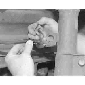
Fig. 1: Remove the retaining clip securing the rubber brake hose to the strut

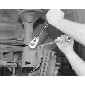
Fig. 2: Using a socket and a backup wrench, remove the two strut-to-steering knuckle nuts and bolts

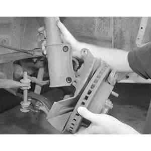
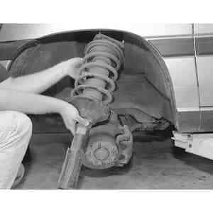
Fig. 3: Separate the lower portion of the strut from the steering knuckle

  1. Raise and safely support the vehicle. Remove the wheel and tire assembly.
  2. Support the lower control arm with a jack.
  3. Remove the clip attaching the brake hose to the strut and disconnect the hose from the strut.
  4. Remove the strut-to-knuckle attaching bolts and nuts.

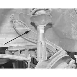
    Fig. 4: After separating the strut from the knuckle, support the knuckle with a strong piece of wire to prevent possible stress damage to the rubber brake hose

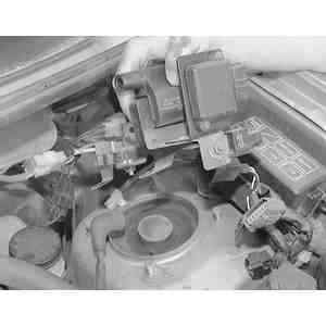
    Fig. 5: Remove the igniter, ignition coil and mounting bracket assembly from the top of the strut tower to access the upper strut mounting nuts

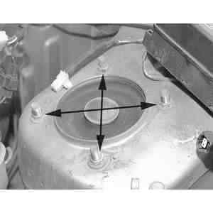
    Fig. 6: Remove the four upper strut mounting nuts while supporting the strut assembly

  5. Working in the engine compartment, remove the 4 attaching nuts from the strut tower and remove the strut assembly from the vehicle. If necessary, remove any components that can hinder the removal of the strut mounting nuts.
  6. If the strut must be disassembled, or the coil spring removed, refer to the overhaul procedure later in this section.

    Fig. 7: Carefully remove the strut assembly from the vehicle through the fender well

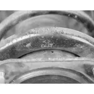
    Fig. 8: Note the marking to indicate how the strut assembly is installed into the vehicle (OUT w/arrow)

    To install:

  7. Assemble the strut according to the overhaul procedure, if necessary.
  8. Install the strut assembly in the strut tower, making sure the white mark on the upper mounting block is in the front-inside direction. Install the attaching nuts and tighten to 34–46 ft. lbs. (47–62 Nm).
  9. Install the strut to the knuckle and tighten the attaching bolts and nuts to 69–86 ft. lbs. (93–117 Nm).
  10. Position the brake hose on the strut and install the clip. Remove the jack from under the lower control arm.
  11. Install the wheel and tire assembly and lower the vehicle. Check the front end alignment.

Previous Next