Previous Next

Steering Linkage

REMOVAL & INSTALLATION

Fig. 1: Navajo 2WD steering linkage assemblies, 4WD models similar

Fig. 2: Pickup power steering linkage components

Idler Arm
PICKUPS
  1. Raise and support the front end on jackstands.
  2. Remove the idler arm-to-center link nut and cotter pin. Disconnect the center link from the idler arm using a ball joint separator.
  3. Unbolt and remove the idler arm.
  4. Install and secure the idler arm. Connect the center link. Always install new cotter pins. Torque the center link nut to 43 ft. lbs. (58 Nm); the frame mounting bolts to 69 ft. lbs. (94 Nm).
Pitman Arm
PICKUPS
  1. Raise and support the front end on jackstands.
  2. Remove the cotter pin and nut attaching the center link to the pitman arm.
  3. Disconnect the center link from the pitman arm with a ball joint separator.
  4. Matchmark the pitman arm and sector shaft.
  5. Remove the pitman arm-to-sector shaft nut and remove the pitman arm. It may be necessary to use a puller.
  6. Install and attach the pitman arm and components. Make sure you align the matchmarks. Tighten the pitman arm-to-sector shaft nut to 130 ft. lbs. (177 Nm); the pitman arm-to-center link nut to 43 ft. lbs. (58 Nm). If the cotter pin does not align, tighten the nut to make it line up, never loosen it!
NAVAJO
  1. As required, raise and safely support the vehicle using jackstands.
  2. Remove the cotter pin and nut from the drag link ball stud at the pitman arm.
  3. Remove the drag link ball stud from the pitman arm using pitman arm removal tool T64P–3590–F or equivalent.
  4. Remove the pitman arm retaining nut and washer. Remove the pitman arm from the steering gear sector shaft using tool T64P–3590–F or equivalent.
  5. Install and secure the pitman arm and components. Torque the pitman arm attaching washer and nut to 170–230 ft. lbs. (231–313 Nm). Torque the drag link ball stud nut to 50–70 ft. lbs. (68–95 Nm) and install a new cotter pin.
  6. Check and adjust front end alignment, as required.
Center (Drag) Link
PICKUPS
  1. Raise and support the front end on jackstands.
  2. Disconnect the center link at the tie rods, pitman arm and idler arm.
  3. Install and secure the center link and components. Tighten all of the nuts to 43 ft. lbs. (58 Nm).
NAVAJO
  1. Raise and support the vehicle using jackstands. Be sure that the front wheels are in the straight ahead position.
  2. Remove the nuts and cotter pins from the ball stud at the pitman arm and steering tie rod. Remove the ball studs from the linkage using pitman arm removal tool T64P–3590–F or equivalent.
  3. Loosen the bolts on the drag link adjusting sleeve. Be sure to count and record the number of turns it takes to remove the drag link.

    To install:

  4. Install the drag link in the same number of turns it took to remove it. Tighten the adjusting sleeve nuts to 30–42 ft. lbs. (41–57 Nm). Be sure that the adjusting sleeve clamps are pointed down approximately 45°.
  5. Position the drag link ball stud in the pitman arm. Position the steering tie rod ball stud in the drag link. With the vehicle wheels in the straight ahead position install and torque the nuts to 50–75 ft. lbs. (68–102 Nm). Install a new cotter pin.
  6. Check and adjust front end alignment, as required.
Tie Rod
NAVAJO
  1. Raise and support the vehicle using jackstands. Be sure that the front wheels are in the straight ahead position.
  2. Remove the nut and cotter pin from the ball stud on the drag link. Remove the ball stud from the drag link using pitman arm removal tool T64P–3590–F or equivalent.
  3. Loosen the bolts on the tie rod adjusting sleeve. Be sure to count and record the number of turns it takes to remove the tie rod from the tie rod adjusting sleeve. Remove the tie rod from the vehicle.

    To install:

  4. Install the tie rod in the tie rod sleeve in the same number of turns it took to remove it. Torque the tie rod adjusting sleeve nuts to 30–42 ft. lbs. (41–57 Nm).
  5. Be sure that the adjusting sleeve clamps are pointed down approximately 45°. Tighten the tie rod ball stud to drag link retaining bolt to 50–75 ft. lbs. (68–102 Nm). Install a new cotter pin.
  6. Check and adjust front end alignment, as required.
Tie Rod Ends
PICKUPS
  1. Loosen the tie rod jam nuts.
  2. Remove and discard the cotter pin from the ball socket end, and remove the nut.
  3. Use a ball joint puller to loosen the ball socket stud from the center link. Remove the stud from the kingpin steering arm in the same way.
  4. Unscrew the tie rod end from the threaded sleeve, counting the number of threads until it's off. The threads may be left or right hand threads. Tighten the jam nuts to 58 ft. lbs. (79 Nm).
  5. To install, lightly coat the threads with grease, and turn the new end in as many turns as were required to remove it. This will give the approximate correct toe-in.
  6. Install the ball socket studs into center link and kingpin steering arm. Tighten the nuts to 43 ft. lbs. (58 Nm). Install a new cotter pin. You may tighten the nut to fit the cotter pin, but don't loosen it.
  7. Check and adjust the toe-in, and tighten the tie rod clamps or jam nuts.
MPV

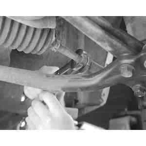
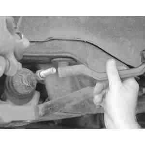
Fig. 3: Using a backup wrench, loosen the jam nut from the tie rod

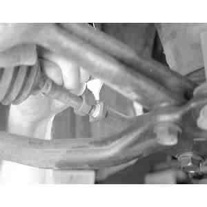
Fig. 4: Matchmark the location of the tie rod end on the tie rod. This will help during installation

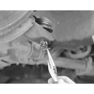
Fig. 5: Remove and discard the cotter pin from tie rod ball stud

  1. Raise and support the front end on jackstands.
  2. Remove the wheels.
  3. Matchmark the tie rod end and tie rod and loosen the locknut.
  4. Loosen the tie rod end ball stud nut and separate the tie rod end from the knuckle arm with a separator tool.
  5. Unscrew the tie rod end, counting the number of turns until it's off, for installation purposes.

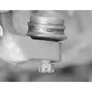
    Fig. 6: Install the castle nut onto the end of the ball stud to prevent the stud from "mushrooming" during removal

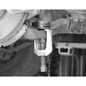
    Fig. 7: Using a puller tool with the castle nut on the end of the ball stud, separate the tie rod end ball joint from the steering knuckle

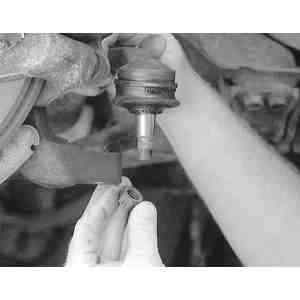
    Fig. 8: Remove the castle nut and pull the tie rod end ball stud straight out of the steering knuckle

    Fig. 9: Count the number of turns required to remove the tie rod end from the tie rod. This will help during the installation process

    To install:

  6. Install the tie rod end onto the tie rod the same number of turns that it took to remove it. Tighten the locknut to 58 ft. lbs. (79 Nm).
  7. Install the ball stud into the steering knuckle. Tighten the ball stud nut to 58 ft. lbs. (79 Nm) and install the cotter pin.
  8. Lower the vehicle and install a new cotter pin. Always advance the nut to align the cotter pin hole. Never back it off. Check the front alignment.
NAVAJO
  1. Raise and support the vehicle using jackstands. Be sure that the front wheels are in the straight ahead position.
  2. Remove the nut and cotter pin from the ball stud on the drag link. Remove the ball stud from the drag link using pitman arm removal tool T64P–3590–F or equivalent.
  3. Loosen the bolts on the tie rod adjusting sleeve. Be sure to count and record the number of turns it takes to remove the sleeve from the ball stud.

    To install:

  4. Install the adjusting sleeve on the tie rod ball stud in the same number of turns it took to remove it. Loosely assemble the ball stud in the spindle arm.
  5. Torque the retaining nuts to 30–42 ft. lbs. (41–57 Nm). Be sure that the adjusting sleeve clamps are pointed down approximately 45°.
  6. With the vehicle wheels in the straight ahead position, install and torque the nut to 50–75 ft. lbs. (68–102 Nm). Install a new cotter pin.
  7. Check and adjust front end alignment, as required.

Previous Next