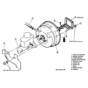
| Fig. 1: Power brake booster removal/installation

|
- Remove the master cylinder and proportioning bypass valve bracket (if equipped).
- Disconnect the vacuum line at the booster.
- Disconnect the pushrod at the brake pedal.
- Unbolt and remove the power booster from the firewall (under the dash).
- Installation is the reverse of removal. Check the clearance between the
master cylinder piston and the power booster pushrod. Clearance should be
0. If not, adjust it at the pushrod. Torque the mounting nuts to 17 ft. lbs.
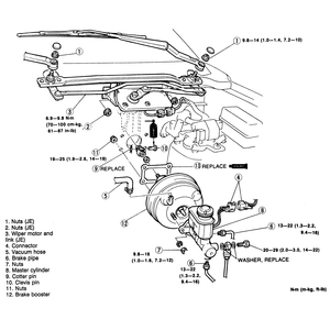
| Fig. 2: Power brake booster removal/installation

|
- Remove the wiper arms.
- Remove the drive link nuts from the top of the cowl.
- Working under the hood, disconnect the battery ground cable.
- Remove the wiper motor and linkage mounting bolts and lift out the assembly.
- Remove the master cylinder.
- Disconnect the pushrod at the pedal.
- Disconnect the vacuum line at the booster.
- Unbolt and remove the power booster from the firewall.
To install:
- Check the clearance between the master cylinder piston and the power booster
pushrod. Clearance should be 0, but the piston should not depress the pushrod.
Adjust the clearance at the pushrod.
- Position a new mounting gasket, coated with sealant, on the firewall.
- Position the vacuum unit on the firewall and install the nuts. Torque the
mounting nuts to 19 ft. lbs.
- Connect the pushrod at the pedal.
- Connect the vacuum line.
- Install the master cylinder.
- Install the wiper motor and linkage. When installing the wiper arms, make
sure that the at-rest position gives a gap of 30mm between the blade tips
and the lower windshield molding.
- Bleed the brakes.
- Disconnect the fluid sensor line.
- Remove the master cylinder.
- Disconnect the pushrod at the pedal.
- Disconnect the vacuum line at the booster.
- Unbolt and remove the power booster from the firewall.
To install:
- Check the clearance between the master cylinder piston and the power booster
pushrod. Clearance should be 0, but the piston should not depress the pushrod.
Adjust the clearance at the pushrod.
- Position a new mounting gasket, coated with sealant, on the firewall.
- Position the vacuum unit on the firewall and install the nuts. Torque the
mounting nuts to 19 ft. lbs.
- Connect the pushrod at the pedal.
- Connect the vacuum line.
- Install the master cylinder.
- Bleed the brakes.
NOTE: Make sure that the booster rubber reaction disc is properly
installed if the master cylinder push rod is removed or accidentally pulled
out.A dislodged disc may cause excessive pedal travel and extreme operation
sensitivity. The disc is black compared to the silver colored valve plunger
that will be exposed after the push rod and front seal is removed. The booster
unit is serviced as an assembly and must be replaced if the reaction disc cannot
be properly installed and aligned, or if it cannot be located within the unit
itself.
- Disconnect the stop lamp switch wiring to prevent running the battery down.
- Support the master cylinder from the underside with a prop.
- Remove the master cylinder-to-booster retaining nuts.
- Loosen the clamp that secures the manifold vacuum hose to the booster check
valve, and remove the hose. Remove the booster check valve.
- Pull the master cylinder off the booster and leave it supported by the prop,
far enough away to allow removal of the booster assembly.
- From inside the cab on vehicles equipped with push rod mounted stop lamp
switch, remove the retaining pin and slide the stop lamp switch, push rod,
spacers and bushing off the brake pedal arm.
- From the engine compartment remove the bolts that attach the booster to
the dash panel.
To install:
- Mount the booster assembly on the engine side of the dash panel by sliding
the bracket mounting bolts and valve operating rod in through the holes in
the dash panel.
NOTE: Make certain that the booster push rod is positioned
on the correct side of the master cylinder to install onto the push pin
prior to tightening the booster assembly to the dash.
- From inside the cab, install the booster mounting bracket-to-dash panel
retaining nuts.
- Position the master cylinder on the booster assembly, install the retaining
nuts, and remove the prop from underneath the master cylinder.
- Install the booster check valve. Connect the manifold vacuum hose to the
booster check valve and secure with the clamp.
- From inside the cab on vehicles equipped with push rod mounted stop lamp
switch, install the bushing and position the switch on the end of the push
rod. Then install the switch and rod on the pedal arm, along with spacers
on each side, and secure with the retaining pin.
- Connect the stop lamp switch wiring.
- Start the engine and check brake operation.


