Previous Next

REMOVAL & INSTALLATION

2-Wheel Drive Pickups
  1. Raise and support the rear end on jackstands.
  2. Remove the drums.
  3. Remove the retracting springs.
  4. Remove the holddown springs and guide pins by turning the collars 90°with a pliers, or spring tool, releasing the springs.
  5. Remove the parking brake link and disconnect the parking brake cable from the lever.
  6. Remove the adjusting pawl and spring.
  7. Remove the shoes, noting in which place the shoe with the longer lining is installed.
  8. Inspect the shoes for cracks, heat checking or contamination by oil or grease. Minimum lining thickness is 1.00mm (0.039 in.). If heat checking or discoloration is noted, the wheel cylinders are probably at fault and will have to be rebuilt or replaced.

    NOTE: Never replace the shoes on one side of the truck, only! Always replace shoes on both sides!

  9. Clean the backing plate with an approved cleaning fluid.
  10. Lubricated the threads of the starwheel with lithium based or silicone based grease. Apply a small dab of lithium or silicone based grease to the pads on which the brake shoes ride.

    To install:

  11. Transfer the parking brake lever to the new shoe.
  12. Installation is the reverse of the removal procedure.
  13. Adjust the brake shoes.

    NOTE: The adjustment should be the same on both wheels.

  14. Adjust the parking brake.
  15. Operate the brake pedal a few times. If the brakes feel at all spongy, bleed the system.
4-Wheel Drive Pickups
  1. Raise and support the rear end on jackstands.
  2. Remove the wheels.
  3. Remove the brake drum.
  4. Disconnect the parking brake cable.
  5. Remove the holddown spring assemblies.
  6. Remove the self-adjusting lever.
  7. Remove the lever link.
  8. Remove the pull-off spring.
  9. Remove the lower shoe-to-shoe spring.
  10. Remove the 2 upper return springs.
  11. Remove the star-wheel adjuster.
  12. Remove the brake shoes and strut.
  13. Remove the parking brake cable lever.
  14. Inspect the shoes for cracks, heat checking or contamination by oil or grease. Minimum lining thickness is 1.00mm (0.039 in.). If heat checking or discoloration is noted, the wheel cylinders are probably at fault and will have to be rebuilt or replaced.

    CAUTION
    Never replace the shoes on one side of the truck, only! Always replace shoes on both sides!

  15. Clean the backing plate with an approved cleaning fluid.
  16. Lubricated the threads of the starwheel with lithium based or silicone based grease. Apply a small dab of lithium or silicone based grease to the pads on which the brake shoes ride.

    To install:

  17. Transfer the parking brake lever to the new shoe.
  18. Installation is the reverse of the removal procedure.
  19. Adjust the brake shoes.

    NOTE: The adjustment should be the same on both wheels.

  20. Adjust the parking brake.
  21. Operate the brake pedal a few times. If the brakes feel at all spongy, bleed the system.
MPV

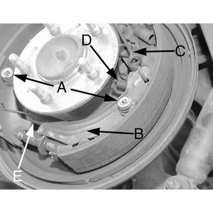
Fig. 1: Remove the following components: (A) hold-down springs, (B) self-adjusting lever, (C) lever link, (D) pull-off spring, (E) lower shoe-to-shoe spring

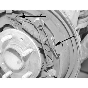
Fig. 2: Remove the 2 upper return springs

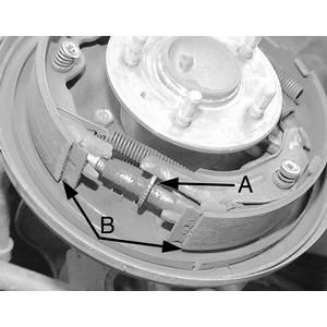
Fig. 3: Remove the (A) star-wheel adjuster, then remove the (B) brake shoes and strut

  1. Raise and support the rear end on jackstands.
  2. Remove the wheels.
  3. Remove the brake drum.
  4. Disconnect the parking brake cable.
  5. Remove the holddown spring assemblies.
  6. Remove the self-adjusting lever.
  7. Remove the lever link.
  8. Remove the pull-off spring.
  9. Remove the lower shoe-to-shoe spring.
  10. Remove the 2 upper return springs.
  11. Remove the star-wheel adjuster.
  12. Remove the brake shoes and strut.
  13. Remove the parking brake cable lever.
  14. Inspect the shoes for cracks, heat checking or contamination by oil or grease. Minimum lining thickness is 1.00mm. If heat checking or discoloration is noted, the wheel cylinders are probably at fault and will have to be rebuilt or replaced.

    CAUTION
    Never replace the shoes on one side of the truck, only! Always replace shoes on both sides!

  15. Clean the backing plate with an approved cleaning fluid.
  16. Lubricated the threads of the starwheel with lithium based or silicone based grease. Apply a small dab of lithium or silicone based grease to the pads on which the brake shoes ride.

    To install:

  17. Transfer the parking brake lever to the new shoe.
  18. Installation is the reverse of the removal procedure.
  19. Adjust the brake shoes.

    NOTE: The adjustment should be the same on both wheels.

  20. Adjust the parking brake.
  21. Operate the brake pedal a few times. If the brakes feel at all spongy, bleed the system.
Navajo
  1. Raise and safely support the vehicle. Remove the wheel and tire assembly and the brake drum.
  2. Pull backward on the adjusting lever cable to disengage the adjusting lever from the adjusting screw. Move the outboard side of the adjusting screw upward and back off the pivot nut as far as it will go.
  3. Pull the adjusting lever, cable and automatic adjuster spring down and toward the rear to unhook the pivot hook from the large hole in the secondary shoe web. Do not pry the pivot hook from the hole.
  4. Remove the automatic adjuster spring and adjusting lever.
  5. Remove the secondary shoe-to-anchor spring using a suitable brake spring removal/installation tool. Using the tool, remove the primary shoe-to-anchor spring and unhook the cable anchor. Remove the anchor pin plate, if equipped.
  6. Remove the cable guide from the secondary shoe.
  7. Remove the shoe hold-down springs, shoes, adjusting screw, pivot nut and socket. Note the color and position of each hold-down spring so they can be reassembled in the same position.
  8. Remove the parking brake link and spring. Disconnect the parking brake cable from the parking brake lever.
  9. Remove the secondary brake shoe. Remove the retainer clip and spring washer and remove the parking brake lever.

    To install:

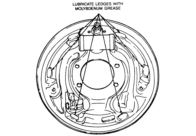
    Fig. 4: Apply a small dab of lube on the backing plate platforms

  10. Clean the backing plate ledge pads and sand lightly. Apply a light coating of high temperature lithium grease to the points where the brake shoes touch the backing plate.
  11. Install the parking brake lever on the secondary shoe and secure with the spring washer and retaining clip.
  12. Position the brake shoes on the backing plate and install the hold-down spring pins, springs and cups. Install the parking brake link, spring and washer. Connect the parking brake cable to the parking brake lever.
  13. Install the anchor pin plate, if equipped, and place the cable anchor over the anchor pin with the crimped side toward the backing plate.
  14. Install the primary shoe-to-anchor spring using the brake spring removal/installation tool.
  15. Install the cable guide on the secondary shoe with the flanged hole fitted into the hole in the secondary shoe. Thread the cable around the cable guide groove.

    NOTE: Make sure the cable is positioned in the groove and not between the guide and shoe web.

  16. Install the secondary shoe-to-anchor (long) spring.

    NOTE: Make sure the cable end is not cocked or binding on the anchor pin when installed. All parts should be flat on the anchor pin.

  17. Apply high temperature lithium grease to the threads and the socket end of the adjusting screw. Turn the adjusting screw into the adjusting pivot nut to the end of the threads and then loosen, 12 turn.
  18. Place the adjusting socket on the screw and install the assembly between the shoe ends with the adjusting screw nearest the secondary shoe.

    NOTE: Be sure to install the adjusting screw on the same side of the vehicle from which it came. To prevent incorrect installation, the socket end of each adjusting screw is stamped with R or L, to indicate installation on the right or left side of the vehicle. The adjusting pivot nuts have lines machined around the body of the nut, 2 lines indicating the right side nut and 1 line indicating the left side nut.

  19. Hook the cable hook into the hole in the adjusting lever from the outboard plate side. The adjusting levers are also stamped with an R or L to indicate right or left side installation.
  20. Place the hooked end of the adjuster spring in the large hole in the primary shoe web and connect the loop end of the spring to the adjuster lever hole.
  21. Pull the adjuster lever, cable and automatic adjuster spring down toward the rear to engage the pivot hook in the large hole in the secondary shoe web.
  22. After installation, check the action of the adjuster by pulling the section of the cable between the cable guide and the adjusting lever toward the secondary shoe web far enough to lift the lever past a tooth on the adjusting screw wheel. The lever should snap into position behind the next tooth and releasing the cable should cause the adjuster spring to return the lever to its original position. This return action will turn the adjusting screw 1 tooth.
  23. If pulling the cable does not produce the action described in Step 22 or if lever action is sluggish instead of positive and sharp, check the position of the lever on the adjusting screw toothed wheel. With the brake in a vertical position, anchor at the top, the lever should contact the adjusting wheel 1 tooth above the center line of the adjusting screw. If the contact point is below the center line, the lever will not lock on the adjusting screw wheel teeth and the screw will not turn as the lever is actuated by the cable.
  24. To find the cause of the condition described in Step 23, proceed as follows:
    1. Check the cable and fittings. The cable should completely fill or extend slightly beyond the crimped section of the fittings. If this does not happen, the cable assembly may be damaged and should be replaced.
    2. Check the cable guide for damage. The cable groove should be parallel to the shoe web and the body of the guide should lie flat against the web. Replace the guide if it shows damage.
    3. Check the pivot hook on the lever. The hook surfaces should be square with the body on the lever for proper pivoting. Repair the hook or replace the lever if the hook shows damage.
    4. Be sure the adjusting screw socket is properly seated in the notch in the shoe web.
  25. Adjust the brake shoes using either a brake adjustment gauge or manually with the drums installed.
  26. If using a brake adjustment gauge, proceed as follows:
    1. Measure the inside diameter of the brake drum with the gauge.
    2. Reverse the tool and adjust the brake shoes until they touch the gauge. The gauge contact points on the shoes must be parallel to the vehicle with the center line through the center of the axle.
    3. Install the drum and wheel and tire assembly. Lower the vehicle.
    4. Apply the brakes sharply several times while driving the vehicle in reverse. Check brake operation by making several stops while driving forward.
  27. If manually adjusting the brakes, proceed as follows:
    1. Install the brake drum and wheel and tire assembly.
    2. Remove the cover from the adjusting hole at the bottom of the backing plate and turn the adjusting screw, using a suitable brake adjusting tool, to expand the brake shoes until they drag against the brake drum.
    3. When the shoes are against the drum, insert a narrow prybar through the brake adjusting hole and disengage the adjusting lever from the adjusting screw. While holding the adjusting lever away from the adjusting screw, loosen the adjusting screw with the brake adjusting tool, until the drum rotates freely without drag.
    4. Install the adjusting hole cover and lower the vehicle.
    5. Apply the brakes. If the pedal travels more than halfway to the floor, there is too much clearance between the brake shoes and drums. Repeat the adjustment procedure.

Previous Next