NOTE: Before installing the cylinder heads, have them cleaned
and professionally checked. If there is a problem, generally, it will not go
away by simply installing new gaskets. Cylinder heads can and do warp, which
is the major cause of gasket failure. This is usually due to overheating.
- Disconnect the negative battery cable.
- Drain cooling system.
CAUTION
When draining the coolant, keep in mind that cats and dogs are attracted
by ethylene glycol antifreeze, and are quite likely to drink any that is
left in an uncovered container or in puddles on the ground. This will prove
fatal in sufficient quantity. Always drain the coolant into a sealable container.
Coolant should be reused unless it is contaminated or several years old.
- Remove air cleaner assembly.
- Remove the heater hose-to-valve cover retaining screws.
- Label and remove the spark plug wires.
- Remove the spark plugs.
- Label and disconnect all of the upper engine components and alternator wiring
harnesses.
- Disconnect required vacuum hoses.
- Remove dipstick tube and bracket.
- Remove the valve cover.
- Remove intake manifold retaining bolts.
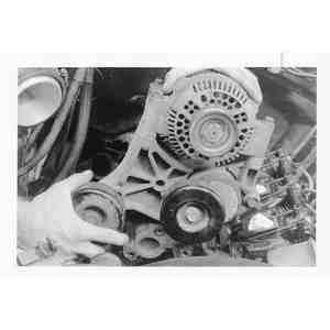
- Loosen alternator retaining bolts and remove belt from the pulley. Remove
mounting bracket retaining bolts to the head.
- Remove the upper radiator hose from the vehicle.
- Remove the timing belt cover. For power steering-equipped vehicles, unbolt
the power steering pump bracket and position it off to the side.
- Loosen the timing belt idler retaining bolts. Position idler in the unloaded
position and tighten the retaining bolts.
- Remove the timing belt.
- Remove four nuts and/or stud bolts retaining heat stove to exhaust manifold.
- Remove the eight exhaust manifold retaining bolts.
- Remove the timing belt idler and two bracket bolts.
- Remove the timing belt idler spring stop from the cylinder head.
- Disconnect the oil sending unit lead wire.
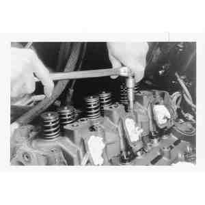
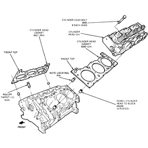
- Remove the cylinder head retaining bolts.
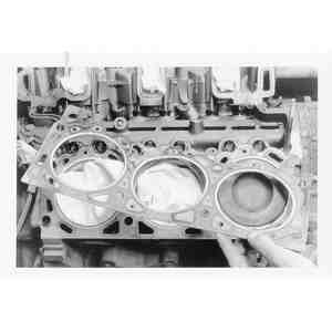
- Remove the cylinder head.
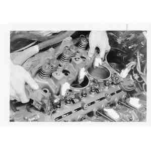
- Clean the cylinder head, intake manifold and exhaust manifold gasket surfaces.
- Blow oil out of the cylinder head bolt block hoses.
- Clean valve cover gasket surface on the head.
- Check cylinder head for flatness.
To install:
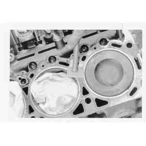
- Position head gasket on the block.
- Clean rocker arm cover (cam cover).
- Install valve cover gasket to the valve cover.
- Position cylinder head to block.
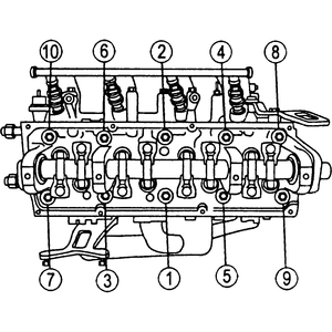
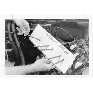
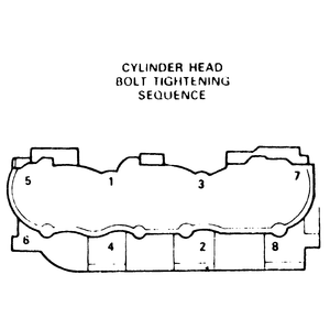
- Install cylinder head retaining bolts and tighten, in three steps, in sequence,
to the following specifications:
- Step 1: 52 ft. lbs. (70 Nm)
- Step 2: 52 ft. lbs. (70 Nm)
- Step 3: Turn all cylinder head bolts an additional 90–100°
| Fig. 1: 2.3L cylinder head bolt tightening sequence
|
- Connect oil sending unit lead wires.
- Install the timing belt idler spring stop to the cylinder head.
- Position the timing belt idler to the cylinder head, and install its retaining
bolts.
- Install the eight exhaust manifold retaining bolts and/or stud bolts.
- Install four nuts and/or stud bolts retaining heat stove to exhaust manifold.
- Install the timing belt.
- Install the timing belt cover.
- Install the upper radiator hose and radiator and tighten the retaining clamps.
- Position the alternator bracket to cylinder head and install its retainers.
- If removed, position the power steering pump bracket to the engine and install
its attaching bolts.
- Install the accessory drive belt.
- Position the intake manifold to the cylinder head, and install its retaining
bolts.
- Install the valve cover.
- Install the spark plugs.
- Install the dipstick tube and bracket.
- Connect the appropriate vacuum hoses.
- Connect all of the upper engine components and alternator wiring harnesses.
- Position and connect the spark plug wires.
- Install the heater hose-to-valve cover retaining screws.
- Fill and bleed the cooling system.
- Install the air cleaner.
- Connect the negative battery cable.
- Start the engine and check for leaks.
NOTE: According to the manufacturer, you must use new cylinder
head bolts when installing the head.
- Disconnect the battery ground cable.
- Relieve the fuel system pressure.
- Drain the cooling system.
CAUTION
When draining the coolant, keep in mind that cats and dogs are attracted
by ethylene glycol antifreeze, and are quite likely to drink any that is
left in an uncovered container or in puddles on the ground. This will prove
fatal in sufficient quantity. Always drain the coolant into a sealable container.
Coolant should be reused unless it is contaminated or several years old.
- Loosen the water pump pulley bolts.
- Remove the accessory drive belt.
- Remove the cooling fan assembly.
- Remove the upper and lower intake manifold.
- Label and remove the spark plug wires.
- Remove the spark plugs.
- Remove the oil level dipstick tube.
- Remove the EGR valve-to-exhaust manifold tube.
- Remove the valve cover.
- Remove the drive belt.
| Fig. 2: Disengage the engine control sensor wiring
harness from the A/C compressor
|
| Fig. 3: Remove the A/C compressor mounting bolts
|
- Disengage the engine control sensor wiring harness from the A/C compressor.
NOTE: The official Mazda factory repair information recommends
recovering the A/C refrigerant so that the A/C hoses can be disconnected
for the purpose of removal of the compressor from the vehicle. However,
in order to remove the cylinder head, it may only be necessary to remove
the compressor from the mounting bracket and move it off to the side without
disconnecting any hoses. If this is the case, no refrigerant recovery is
necessary. If the hoses must be disconnected, the refrigerant can only be
recovered by a technician certified to do this type of procedure.
- Remove the A/C compressor from the mounting bracket and position it aside.
It may be possible to hold the compressor off to the side without disconnecting
any refrigerant hoses. However, if the refrigerant hoses must be disconnected,
the A/C system must be evacuated, which requires taking the vehicle to a professional
shop for a technicion who is certified to perform these procedures using official
refrigerant recovery equipment.
- Remove the A/C compressor mounting bracket with the power steering pump
attached and position it out of the way.
- Remove the alternator.
- Remove the upper and lower radiator hoses. Remove the heater water hose
from the inlet tube on the water pump.
- Remove the water pump inlet tube.
- Remove the alternator mounting bracket.
- Remove the ignition coil packs and mounting bracket.
- Remove the timing belt cover.
- Remove the timing belt.
- Remove the exhaust manifold.
- Remove and discard the cylinder head mounting bolts.
- Remove and discard the cylinder head gasket.
- Check cylinder head for flatness.
To install:
- Clean the head gasket mating surfaces.
- Position the new head gasket on the block.
- Position the cylinder head onto the engine block.
| Fig. 4: Cylinder head bolt tightening sequence
|
- Install new cylinder head retaining bolts and tighten, in three steps, in
sequence, to the following specifications:
- Step 1: 52 ft. lbs. (70 Nm)
- Step 2: 52 ft. lbs. (70 Nm)
- Step 3: Turn all cylinder head bolts an additional 90–100°
- Install the exhaust manifold.
- Install the timing belt.
- Install the timing belt cover.
- Install the mounting bracket and ignition coil packs.
- Install the alternator mounting bracket and tighten the mounting bolts.
- Install the water pump inlet tube. Connect the heater water hose to the
inlet tube.
- Install the upper and lower radiator hoses. Tighten the hose clamps.
- Install the alternator.
- Install the A/C compressor mounting bracket and tighten the mounting bolts.
- Install the A/C compressor to the mounting bracket and tighten the mounting
bolts. Connect the refrigerant hoses, if disconnected.
- Plug in the engine control sensor wiring harness connector to the compressor.
- Install the drive belt.
- Install the valve cover.
- Install the EGR valve-to-exhaust manifold tube.
- Install the oil level dipstick tube.
- Install the spark plugs and connect the spark plug wires.
- Install the lower and upper intake manifold.
- Install the cooling fan assembly.
- Install the accessory drive belt.
- Tighten the water pump pulley bolts.
- Fill the cooling system bleed the system.
- Connect the battery ground cable.
- Operate the engine at fast idle and check for oil, fuel and coolant leaks.
- If necessary, have the A/C system recharged.
NOTE: According to the manufacturer, you must use new cylinder
head bolts when installing the heads.
- Drain the cooling system (engine cold) into a clean container and save the
coolant for reuse.
CAUTION
When draining the coolant, keep in mind that cats and dogs are attracted
by ethylene glycol antifreeze, and are quite likely to drink any that is
left in an uncovered container or in puddles on the ground. This will prove
fatal in sufficient quantity. Always drain the coolant into a sealable container.
Coolant should be reused unless it is contaminated or several years old.
- Disconnect the battery ground cable.
- Remove the air cleaner.
- Relieve fuel pressure. Disconnect fuel lines as necessary. Mark vacuum line
location and remove lines.
- Disconnect upper and lower radiator hoses–position out of the way.
- Label and remove the ignition wires from the spark plugs and locating studs.
- If equipped, mark the distributor housing to block and note rotor position.
Remove the distributor.
- Remove coil assembly.
- Remove the throttle body. See Section 5.
- Remove the accessory drive belt.
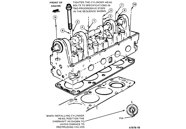
- If the left-hand cylinder head is being removed:
- Remove the power steering pump and bracket assembly. DO NOT disconnect
the hoses. Tie the assembly out of the way.
- Remove the engine oil dipstick and tube. Rotate or remove tube assembly.
- Remove the fuel line retaining bracket bolt from the front of cylinder
head.
- If the right-hand head is being removed:
- Disconnect alternator electrical harnesses.
- Remove belt tensioner assembly.
- Remove the alternator and bracket.
- Remove hose from valve cover to oil fill adapter.
- Remove the spark plugs.
- Remove the exhaust manifold(s).
- Remove the rocker arm covers as previously described.
- Loosen rocker arm fulcrum retaining bolts enough to allow the rocker arm
to be lifted off the pushrod and rotate to one side.
NOTE: Regardless of which cylinder head is being removed,
the #3 cylinder intake valve pushrod must be removed to allow removal of
the intake manifold.
- Remove the pushrods, keeping them in order so they may be installed in their
original locations.
- Remove the intake manifold as outlined. Refer to the necessary service procedure.
- Loosen the cylinder head attaching bolts in reverse of the torque sequence,
then remove the bolts and lift off the cylinder head(s). Remove and discard
the old cylinder head gasket(s).
To install:
- Clean the cylinder heads, intake manifold, valve rocker arm cover and cylinder
block gasket surfaces of all traces of old gasket material and/or sealer.
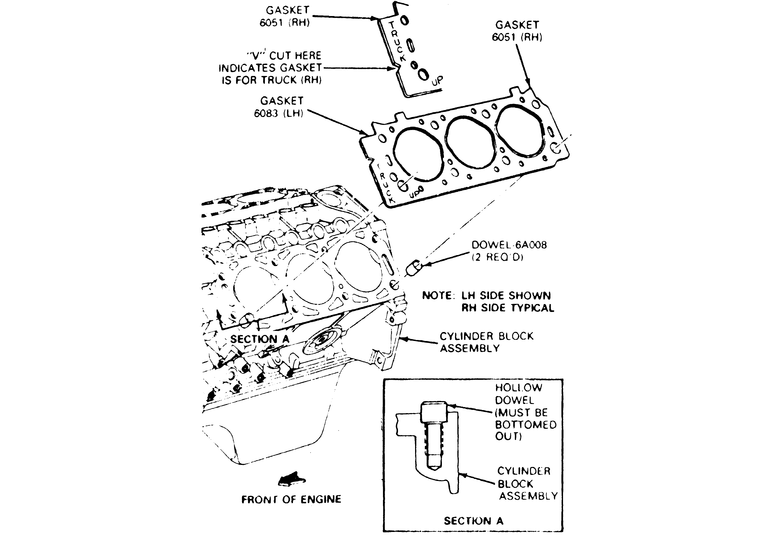
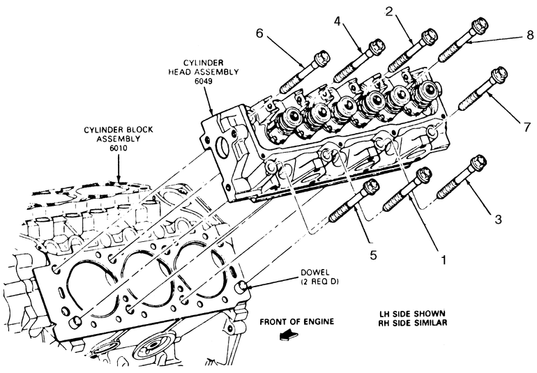
- Lightly oil all bolt and stud bolt threads except those specifying special
sealant. Position the new head gasket(s) on the cylinder block, using the
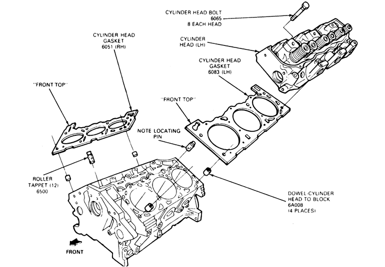
dowels for alignment. The dowels should be replaced if damaged.
| Fig. 5: Cylinder head gasket positioning for the
3.0L
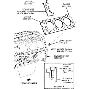
|
| Fig. 6: Cylinder head installation & bolt torque
sequence for the 3.0L

|
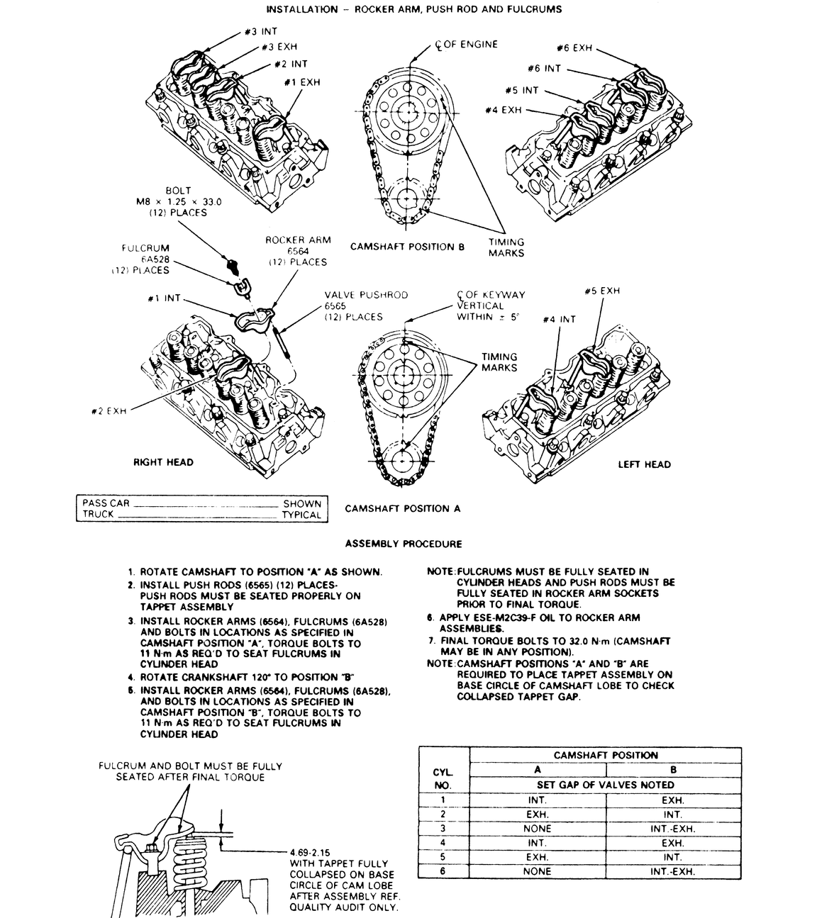
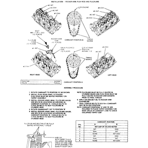
| Fig. 7: Valve rocker arm installation procedure and
collapsed lifter gap clearance check for the 3.0L engine
|
- Position the cylinder head(s) on the block and install new attaching bolts.
Tighten the head bolts in sequence to 59 ft. lbs. (80 Nm). Back off all bolts
one full turn (360 degrees). Retighten the cylinder head bolts in sequence,
in two steps to 37 ft. lbs. (50 Nm). Final tighten to 68 ft. lbs. (92 Nm).
- Install intake manifold as outlined.
- Dip each pushrod in heavy engine oil then install the pushrods in their
original locations.
- For each valve, rotate the crankshaft until the tappet rests on the heel
(base circle) of the camshaft lobe before tightening the fulcrum attaching
bolts. Position the rocker arms over the pushrods. Install the fulcrums (tighten
to 8 ft. lbs. to seat fulcrum) and then tighten the fulcrum attaching bolts
to 24 ft. lbs. (32 Nm). Refer to the necessary illustration for details if
necessary.
WARNING
The fulcrums must be fully seated in the cylinder head and pushrods must
be seated in the rocker arm sockets prior to final tightening.
- Lubricate all rocker arm assemblies with heavy engine oil. If the original
valve train components are being installed, a valve clearance check is not
required. If, however, a component has been replaced, the valve clearance
should be checked.
- Install the exhaust manifold(s).
- Install the dipstick tube and spark plugs.
- Position the rocker arm cover with a new gasket on the cylinder head and
install the retaining bolts. Note the location of the spark plug wire routing
clip stud bolts.
- Install the injector harness.
- If equipped, install the distributor.
- Install the ignition coil assembly.
- Install the spark plug wires.
- Install the throttle body and new gasket. Refer to the necessary service
procedures.
- If the left hand cylinder head was removed, perform the following:
- Install the fuel line retaining bracket bolt to the front of cylinder
head. Torque to 26 ft. lbs. (35 Nm).
- Install the engine oil dipstick and tube assembly.
- Install the power steering pump and bracket assembly.
- If the right hand cylinder head was removed, perform the following:
- Install hose from valve cover to oil fill adapter.
- Install the alternator and bracket.
- Install belt tensioner assembly.
- Reconnect alternator electrical harnesses.
- Install the accessory drive belt.
- Connect fuel lines. Install fuel line safety clips.
- Install all radiator hoses. Connect vacuum lines.
- Drain and change engine oil.
CAUTION
The EPA warns that prolonged contact with used engine oil may cause a number
of skin disorders, including cancer! You should make every effort to minimize
your exposure to used engine oil. Protective gloves should be worn when
changing the oil. Wash your hands and any other exposed skin areas as soon
as possible after exposure to used engine oil. Soap and water, or waterless
hand cleaner should be used.
- Install the air cleaner.
- Fill and bleed the cooling system.
- Connect the battery ground cable.
- Start the engine and check for leaks. If equipped with distributor ignition,
verify base ignition timing.
- Drain the cooling system (engine cold) into a clean container and save the
coolant for reuse.
CAUTION
When draining the coolant, keep in mind that cats and dogs are attracted
by ethylene glycol antifreeze, and are quite likely to drink any that is
left in an uncovered container or in puddles on the ground. This will prove
fatal in sufficient quantity. Always drain the coolant into a sealable container.
Coolant should be reused unless it is contaminated or several years old.
- Disconnect the battery ground cable.
- Remove the air cleaner.
- Remove the rocker arm covers as previously described.
- Remove the upper and lower intake manifolds as described earlier.
- If the left cylinder head is being removed:
- Remove the accessory drive belt.
- Remove the air conditioning compressor.
- Remove the power steering pump and bracket assembly. DO NOT disconnect
the hoses. Tie the assembly out of the way.
- Remove the spark plugs.
| Fig. 8: After removing the intake manifold, loosen
the accessory mounting bracket bolts . . .
|
| Fig. 9: . . . then remove the bracket and accessory
|
- If the right head is being removed:
- Remove the accessory drive belt.
- Remove the alternator and bracket.
- Remove the ignition coil pack and bracket.
- Remove the spark plugs.
- Remove the exhaust manifold(s).
| Fig. 10: Remove the rocker shafts and, keeping them
in order, the pushrods
|
- Remove the rocker shaft assembly.
- Remove the pushrods, keeping them in order so they may be installed in their
original locations.
| Fig. 11: Loosen and remove the cylinder head attaching
bolts . . .
|
| Fig. 12: . . . then lift the cylinder head from the
engine
|
- Loosen the cylinder head attaching bolts in reverse of the torque sequence,
then remove the bolts and discard them. They cannot be re–used.
- Lift off the cylinder head(s).
| Fig. 13: Remove and discard the old cylinder head
gasket
|
- Remove and discard the old cylinder head gasket(s).
To install:
- Clean the cylinder heads, intake manifolds, valve rocker arm cover and cylinder
block gasket surfaces of all traces of old gasket material and/or sealer.
Refer to the following overhaul procedures for cylinder head component removal,
valve replacement, resurfacing, etc.
| Fig. 14: With rags placed in the cylinder bores,
scrape the gasket mating surfaces clean
|
- Lightly oil all bolt and stud bolt threads except those specifying special
sealant. Position the new head gasket(s) on the cylinder block, using the
dowels for alignment. The dowels should be replaced if damaged.
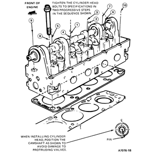
| Fig. 15: Cylinder head installation for the 4.0L
engine
|
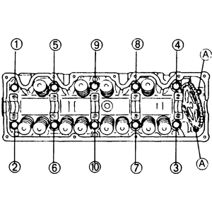
| Fig. 16: Cylinder head torque sequence for the 4.0L
engine
|
| Fig. 17: Lower intake manifold torque sequence for
the 4.0L engine
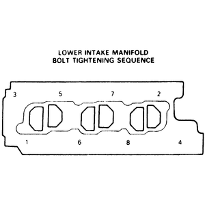
|
NOTE: The cylinder head(s) and intake manifold are torqued
alternately and in sequence, to assure a correct fit and gasket crush.
- Position the cylinder head(s) on the block.
- Apply a bead of RTV silicone gasket material to the mating joints of the
head and block at the 4 corners. Install the intake manifold gasket and again
apply the sealer.
NOTE: This sealer sets within 15 minutes, so work quickly!
- Install the lower intake manifold.
- Tighten the intake manifold fasteners, in sequence, to 36–72 inch
lbs. (4–8 Nm).
WARNING
Do not re–use the old head bolts. ALWAYS use new head bolts!
- Tighten the head bolts, in sequence, to 59 ft. lbs. (80 Nm).
- Tighten the intake manifold fasteners, in sequence, to 6–11 ft. lbs.
(8–15 Nm).
- Tighten the head bolts, in sequence, an additional 80–85 degrees tighter.
85 degrees is a little less than 1⁄4 turn, 1⁄4 turn
would equal 90 degrees.
- Tighten the intake manifold fasteners, in sequence, to 11–15 ft. lbs.
(15–20 Nm); then, in sequence, to 15–18 ft. lbs. (20–24
Nm).
- Dip each pushrod in heavy engine oil then install the pushrods in their
original locations.
- Install the rocker arm/shaft assembly(ies).
- Apply another bead of RTV sealer at the 4 corners where the intake manifold
and heads meet.
- Install the valve covers.
- Install the upper intake manifold. Tighten the nuts to 15–18 ft. lbs.
(20–24 Nm).
- Install the exhaust manifold(s).
- Install the spark plugs and wires.
- If the left head was removed, install the power steering pump, compressor
and drive belt.
- If the right head was removed, install the coil pack and bracket, alternator
and bracket, and the drive belt.
- Install the air cleaner.
- Fill the cooling system.
NOTE: At this point, it's a good idea to change the engine
oil. Coolant contamination of the engine oil often occurs during cylinder
head removal.
- Connect the battery ground cable.
- Start the engine and check for leaks.
- Properly relieve the fuel system pressure.
CAUTION
Never smoke when working around gasoline! Avoid all sources of sparks or
ignition. Gasoline vapors are EXTREMELY volatile!
- Disconnect the negative battery cable.
- Remove the air cleaner assembly.
- Drain the coolant.
- Position the engine at TDC on the compression stroke so all the pulley matchmarks
are aligned.
- Remove the accelerator cable. Remove the air intake pipe and resonance chamber.
- Remove the accessory drive belts and A/C belt idler.
- Remove the upper radiator hose.
- Remove the brake vacuum hose.
- Remove the spark plug wires.
- Remove the spark plugs.
- Remove the oil cooler coolant hose.
- Remove the canister hose.
- Remove the fuel lines.
- Disconnect the oxygen sensor.
- Remove the solenoid valves.
- Disconnect the emissions harness.
- Remove the rocker cover. Check to ensure the engine is set on TDC. The timing
mark on the camshaft sprocket should be 90 degrees to the right, parallel
to the top of the cylinder head. Make sure the yellow crankshaft pulley timing
mark is aligned with the indicator pin.
- Mark the position of the distributor rotor in relation to the distributor
housing, and the distributor housing in relation to the cylinder head. Remove
the distributor. Do not rotate the engine after distributor removal.
- Hold the crankshaft pulley with a suitable tool and remove the distributor
drive gear/camshaft pulley retaining bolt and the drive gear. Remove the upper
timing cover assembly.
- Push the timing chain adjuster sleeve in towards the left, and insert a
0.0787 in. (2mm) diameter x 1.77 in. (45mm) long pin into the lever hole to
hold it in place.
- Wire the chain to the pulley and remove the pulley from the camshaft. Do
not allow the sprocket and chain to fall down into the engine and cause the
chain to become disengaged from the crankshaft sprocket.
- Remove the intake manifold bracket.
- Disconnect the exhaust pipe.
- Remove the 2 front head bolts.
| Fig. 18: Cylinder head bolt removal sequence
|
- Remove the remaining head bolts starting from the rear and working around
toward the center of the head.
- Lift off the head.
- Discard the head gasket.
- Thoroughly clean the mating surfaces of the head and block.
- Check the head and block for flatness with a straightedge.
To install:
- Apply RTV sealer to the top front of the block.
- Place a new head gasket on the block.
- Position the head on the block.
- Clean the head bolts and apply oil to the threads.
| Fig. 19: Cylinder head bolt tightening sequence
|
- Tighten the head bolts, in 2 even steps, to 64 ft. lbs. (87 Nm).
- Tighten the 2 front bolts, to 17 ft. lbs. (23 Nm).
- Place the camshaft pulley on the camshaft and tighten the bolt to to 95
inch lbs. (11 Nm); the nut to 87 inch lbs. (10 Nm).
- Connect the exhaust pipe.
- Install the intake manifold bracket.
- Install the upper timing cover assembly.
- Install the distributor.
- Install the rocker cover.
- Connect the emissions harness.
- Install the solenoid valves.
- Connect the oxygen sensor.
- Install the fuel lines.
- Install the canister hose.
- Install the oil cooler coolant hose.
- Install the spark plugs.
- Install the spark plug wires.
- Install the brake vacuum hose.
- Install the upper radiator hose.
- Install the accessory drive belts.
- Install the accelerator cable.
- Fill the cooling system.
- Install the air cleaner assembly.
- Connect the negative battery cable.
CAUTION
Fuel injection systems remain under pressure after the engine has been turned
OFF. Properly relieve fuel pressure before disconnecting any fuel lines. Failure
to do so may result in fire or personal injury.
CAUTION
Do not allow fuel spray or fuel vapors to come in contact with a spark or open
flame. Keep a dry chemical fire extinguisher nearby. Never store fuel in an
open container due to risk of fire or explosion.
- Position the engine at TDC on the compression stroke.
- Properly relieve the fuel system pressure.
- Disconnect the negative battery cable.
- Remove the air cleaner assembly.
- Disconnect the accelerator cable.
- Drain the cooling system.
- Remove the spark plug wires.
- Remove the fresh air duct assembly.
- Remove the cooling fan and radiator cowling.
- Remove the drive belts.
- Remove the air conditioning compressor idler pulley. If necessary, remove
the compressor and position it to the side.
- Remove the crankshaft pulley and baffle plate.
- Remove the coolant bypass hose.
- Remove the upper radiator hose.
- Remove the timing belt cover assembly retaining bolts. Remove the timing
belt cover assembly and gasket.
- Turn the crankshaft to align the mating marks of the pulleys.
- Remove the upper idler pulley.
- Remove the timing belt. If reusing the belt be sure to mark the direction
of rotation.
- Disconnect and plug canister, brake vacuum and fuel hoses. If equipped with
automatic transmission, disconnect the automatic transmission vacuum hose.
- Remove the 3-way solenoid valve assembly and disconnect all engine harness
connector and grounds.
- If equipped with automatic transmission, remove the dipstick. Disconnect
the required vacuum hoses. Disconnect the accelerator linkage.
- Remove the distributor and the EGR pipe.
- Remove the 6 extension manifolds. Remove the O-rings from the extension
manifolds and replace with new ones. Remove the intake manifold by loosening
the retaining bolts in the proper sequence.
- Remove the cylinder head cover, gasket and seal washers.
- Remove the center exhaust pipe insulator and pipe. Disconnect the exhaust
manifold retaining bolts. Remove the exhaust manifold with insulator.
- Remove the seal plate.
| Fig. 20: Cylinder head bolt removal sequence
|
- Remove the cylinder head retaining bolts in the proper sequence in 2 or
3 stages. Remove the cylinder head from the vehicle.
- Thoroughly clean the cylinder head and cylinder block contact surfaces to
remove any dirt or oil. Check the cylinder head for warpage and cracks. The
maximum allowable warpage is 0.10mm. Inspect the cylinder head bolts for damaged
threads and make sure they are free from grease and dirt. After the bolts
are cleaned, measure the length of each bolt and replace out of specifications
bolts as required.
- Length: Intake — 108mm; Exhaust — 138mm
- Maximum: Intake — 109mm; Exhaust — 139mm
- Check the oil control plug projection at the cylinder block. Projection
should be 0.53–0.57mm. If correct, apply clean engine oil to a new O-ring
and position it on the control plug.
To install:
- Place the new cylinder head gasket on the left bank with the L mark
facing up. Place the new cylinder head gasket on the right bank with the R mark
facing up. Install the cylinder onto the block. Tighten the head bolts in
the following manner:
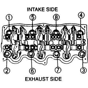
| Fig. 21: Cylinder head bolt tightening sequence
|
- Coat the threads and the seating faces of the head bolts with clean
engine oil.
- Tighten the bolts in the proper sequence to 14 ft. lbs.(19 Nm).
- Paint a mark on the head of each bolt.
- Using this mark as a reference, tighten the bolts in the proper sequence
an additional 90 degrees.
- Repeat the previous step.
- Install the seal plate.
- Install the exhaust manifold with insulator.
- Connect the exhaust manifold retaining bolts.
- Install the center exhaust pipe insulator and pipe.
- Install the cylinder head cover, gasket and seal washers.
- Install the intake manifold by loosening the retaining bolts in the proper
sequence.
- Install the O-rings from the extension manifolds.
- Install the 6 extension manifolds.
- Install the distributor and the EGR pipe.
- If equipped with automatic transmission, install the dipstick. Connect the
required vacuum hoses. Connect the accelerator linkage.
- Install the 3-way solenoid valve assembly and connect all engine harness
connector and grounds.
- Connect the canister, brake vacuum and fuel hoses. If equipped with automatic
transmission, connect the automatic transmission vacuum hose.
- To install the timing belt, first the automatic tensioner must be loaded.
To load the tensioner:
- Place a flat washer on the bottom of the tensioner body to prevent damage
to the body and position the unit on an arbor press.
- Press the rod into the tensioner body. Do not use more than 2000 lbs.
(8900 N) of pressure.
- Once the rod is fully inserted into the body, insert a suitable L-shaped
pin or a small Allen wrench through the body and the rod to hold the rod
in place.
- Remove the unit from the press and install onto the block and torque
the mounting bolt to 14–19 ft. lbs. (19–26 Nm).
- Leave the pin in place, it will be removed later.
- Make sure all the timing marks are aligned properly. With the upper idler
pulley removed, hang the timing belt on each pulley in the order.
- Install the upper idler pulley and torque the mounting bolt to 27–38
ft. lbs. (37–52 Nm).
- Rotate the crankshaft twice in the normal direction of rotation to align
all the timing marks.
- Make sure all the marks are aligned correctly.
- Remove the pin from the auto tensioner. Again turn the crankshaft twice
in the normal direction of rotation and make sure all the timing marks are
aligned properly.
- Check the timing belt deflection by applying 22 lbs. of force. If the deflection
is not 5–7mm, repeat the adjustment procedure.
NOTE: Excessive belt deflection is caused by auto tensioner
failure or an excessively stretched timing belt.
- Install the upper idler pulley.
- Install the timing belt cover assembly and new gasket.
- Install the upper radiator hose.
- Install the coolant bypass hose.
- Install the crankshaft pulley and baffle plate.
- Install the A/C compressor.
- Install the air conditioning compressor idler pulley.
- Install the accessory drive belts.
- Install the cooling fan and radiator cowling.
- Install the fresh air duct assembly.
- Install the spark plug wires.
- Connect and adjust the accelerator cable.
- Fill the cooling system.
- Install the air cleaner assembly.
- Connect the negative battery cable.