Previous Next

Exhaust Manifold

REMOVAL & INSTALLATION

CAUTION
Allow the engine to cool before attempting to remove the manifolds. Serious injury can result from contact with hot exhaust manifolds.

2.3L Engines
  1. Disconnect the negative battery cable.
  2. Remove the air cleaner outlet tube.
  3. Remove the EGR transducer lines at the tube. Loosen and remove the EGR valve-to-exhaust manifold tube.

    Fig. 1: Exploded view of the 2.3L engine exhaust manifold

  4. Disconnect the exhaust pipe from the exhaust manifold.
  5. Remove the two nuts securing the lifting bracket/transducer mount, and remove the bracket.
  6. Remove the exhaust manifold mounting bolts/nuts and remove the manifold.
  7. Install the exhaust manifold in the reverse order. Torque the manifold in sequence in two steps:
2.5L Engines
  1. Disconnect the negative battery cable.
  2. Unplug the wiring harness connector from the Intake Air Temperature (IAT) sensor.
  3. Remove the air cleaner outlet duct.
  4. Disconnect and label any vacuum hoses necessary to gain access to the exhaust manifold.

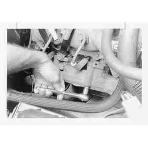
    Fig. 2: Disconnect the EGR tube from the exhaust manifold

  5. Loosen the fitting at the EGR valve and disconnect the fitting at the exhaust manifold.
  6. Disconnect the catalytic converter from the exhaust manifold.
  7. Loosen the 2 mounting nuts and remove the rear engine lifting eye.
  8. Remove the 2 studs and 6 manifold mounting bolts.
  9. Lift the manifold from the cylinder head.
  10. Clean gasket surfaces on the exhaust manifold and the cylinder head.

    To install:

    Fig. 3: Exhaust manifold mounting bolt and stud tightening sequence for the 2.5L engine

  11. Install a new exhaust manifold gasket.
  12. Position the exhaust manifold onto the cylinder head. Install and tighten the 2 studs and 6 mounting bolts, in sequence, in 2 stages to the following specifications:
  13. Install the rear engine lifting eye and tighten the 2 mounting nuts to 15–22 ft. lbs. (20–30 Nm).
  14. Install the catalytic converter to the exhaust manifold and tighten the mounting fasteners.
  15. Connect the EGR tube to the exhaust manifold and tighten the fitting. Tighten the EGR tube fitting at the EGR valve.
  16. Connect all of the vacuum hoses that were disconnected for the removal procedure.
  17. Install the air cleaner outlet duct.
  18. Plug in the wiring harness connector to the IAT sensor.
  19. Connect the negative battery cable.
3.0L Engine (B Series Pick-up)
  1. Disconnect the negative battery cable. Raise and safely support the vehicle as necessary.
  2. Remove the spark plugs.
  3. If removing the left side exhaust manifold remove the oil level indicator tube retaining nut, rotate the dipstick assembly out of the way. Also, if equipped, loosen the EGR tube flare nut at the valve and remove the tube bolt at the manifold.

    Fig. 4: Exploded view of both left and right-hand exhaust manifolds on the 3.0L engine

  4. Remove the manifold to exhaust pipe attaching nuts, then separate the exhaust pipe from the manifold.
  5. Remove the exhaust manifold attaching bolts and the manifold.

    To install:

  6. Clean all gasket mating surfaces.
  7. Lightly oil all bolt and stud threads before installation. If a new manifold is being installed, the oxygen sensor will have to be transferred to the new part.
  8. Position the exhaust manifold on the cylinder head and install the manifold attaching bolts. Tighten them to 19 ft. lbs. (25 Nm).
  9. Connect (replace gasket if so equipped) the exhaust pipe to the manifold, then tighten the attaching nuts to 30 ft. lbs. (41 Nm). TIGHTEN BOTH NUTS IN EQUAL AMOUNTS TO CORRECTLY SEAT INLET PIPE FLANGE.
  10. If installing the left side manifold, install the oil tube dipstick assembly (apply sealer to the tube) as necessary. Also reattach the EGR tube and components if removed.
  11. Install the spark plugs.
  12. Connect the negative battery cable. Start the engine and check for leaks.
4.0L Engine
  1. Disconnect the negative battery cable. Remove the oil level indicator tube bracket.

    Fig. 5: Exploded view of the left-hand exhaust manifold on the 4.0L engine

    Fig. 6: Exploded view of the right-hand exhaust manifold on the 4.0L engine

  2. Raise and safely support the vehicle.

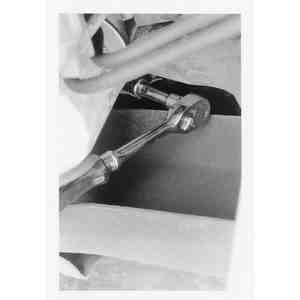
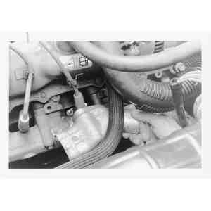
    Fig. 7: To remove the exhaust manifold, first remove the exhaust pipe-to-manifold bolts from underneath

  3. Remove the exhaust pipe–to–manifold bolts.
  4. Lower the vehicle.

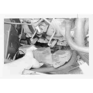
    Fig. 8: Unbolt the hot air intake shroud, which wraps around the manifold and covers some of the attaching bolts

    Fig. 9: Remove the shroud . . .

  5. If removing the left-hand manifold, disconnect the power steering pump hoses.
  6. If removing the right-hand manifold, remove the hot air intake shroud which is bolted around the manifold.

    Fig. 10: . . . then unbolt the manifold . . .

    Fig. 11: . . . and lift it from the engine

  7. Unbolt and remove the manifold.
  8. Clean and lightly oil all fastener threads.
  9. Installation is the reverse of removal. Replace all gaskets if so equipped. Torque the manifold bolts to 19 ft. lbs. (25 Nm); the exhaust pipe nuts to 20 ft. lbs. (27 Nm). TIGHTEN BOTH EXHAUST PIPE RETAINING NUTS IN EQUAL AMOUNTS TO CORRECTLY SEAT INLET PIPE FLANGE.
  10. If installing the left-hand manifold, reconnect the power steering pump hoses, then fill and bleed the system.
  11. Connect the negative battery cable and run the engine to check for leaks.
2.6L Engine

Fig. 12: Exploded view of exhaust system components — 2.6L engine

  1. Disconnect the negative battery cable.
  2. Drain the cooling system.

    CAUTION
    When draining the coolant, always drain the coolant into a sealable container. Coolant should be reused unless it is contaminated or several years old.

  3. Remove the oil dipstick tube.
  4. Remove the coolant bypass pipe.
  5. Disconnect the exhaust pipe from the manifold.
  6. Remove the heat shield.
  7. Unbolt and remove the manifold. Discard the gasket.

    To install:

  8. Clean all mating surfaces. Place a new gasket and exhaust manifold in position and loosely install the mounting bolts. After all of the manifold bolts and attached components are loosely installed, secure all mounting bolts. Torque the bolts to 16–21 ft. lbs. (22–28 Nm).
  9. Install the heat shield and tighten the mounting bolts to 14–22 ft. lbs. (19–30 Nm).
  10. Connect the exhaust pipe to the manifold. Torque the bolts to 28–38 ft. lbs. (38–51 Nm).
  11. Install the coolant bypass pipe.
  12. Install the oil dipstick tube.
  13. Fill and bleed the cooling system.
  14. Connect the negative battery cable.
3.0L Engine (MPV)

Fig. 13: Exploded view of exhaust system components — 3.0L engine

  1. Disconnect the negative battery cable. Wait at least 90 seconds before performing any work.
  2. Raise and safely support the vehicle.
  3. If necessary remove the engine splash shield.
  4. Disconnect the oxygen sensor connector.
  5. Remove the nuts attaching the 3 way pre-catalytic convertor to the main catalytic convertor and the LH exhaust manifold. Remove the 3 way pre-catalytic convertor and the gaskets.
  6. Remove the bolts and the LH and the RH exhaust manifold insulators.
  7. Remove the attaching bolts and nuts and the center exhaust pipe insulators.
  8. Remove the bolts securing the center exhaust manifold to the LH and RH exhaust manifolds. Remove the center exhaust manifold and the gaskets.
  9. Remove the mounting nuts, the LH and the RH exhaust manifolds, and the gaskets.

    To install:

  10. Before installation make sure all mating surfaces are clean of any gasket material.
  11. Install the RH and the LH exhaust manifolds with new gaskets and torque the mounting nuts to 16–20 ft. lbs. (22–36 Nm).
  12. Install the center exhaust manifold with 2 new gaskets to the RH and LH exhaust manifolds. Torque the bolts to 14–18 ft. lbs. (19–24 Nm).
  13. Reinstall the RH and the LH exhaust manifold insulators with the attaching bolts. Torque the bolts to 14–18 ft. lbs.
  14. Install the exhaust insulator to the center exhaust pipe with the bolts and nuts. Torque the bolts and nuts to 14–18 ft. lbs. (19–24 Nm).
  15. Install the 3 way pre-catalytic convertor using new gaskets to the LH exhaust manifold and the main catalytic convertor. Torque the nuts to 28–38 ft. lbs. (38–52 Nm).
  16. Reconnect the oxygen sensor connector.
  17. If necessary, reinstall the engine splash shield.
  18. Safely lower the vehicle and reconnect the negative battery cable.

Previous Next