WARNING
Anytime the upper or lower intake manifold has been removed, cover all openings
with a rag or a sheet of plastic to prevent dirt and debris from falling into
the engine.
| Fig. 1: Exploded view of the upper and lower intake manifold
assemblies on the 2.3L engine
|
The intake manifold is a two–piece (upper and lower) aluminum casting.
Runner lengths are tuned to optimize engine torque and power output. The manifold
provides mounting flanges for the air throttle body assembly, fuel supply manifold,
accelerator control bracket and the EGR valve and supply tube. A vacuum fitting
is installed to provide vacuum to various engine accessories. Pockets for the
fuel injectors are machined to prevent both air and fuel leakage. The following
procedure is for the removal of the intake manifold with the fuel charging assembly
attached.
- Make sure the ignition is off, then drain the coolant from the radiator
(engine cold).
CAUTION
When draining the coolant, keep in mind that cats and dogs are attracted
by ethylene glycol antifreeze, and are quite likely to drink any that is
left in an uncovered container or in puddles on the ground. This will prove
fatal in sufficient quantity. Always drain the coolant into a sealable container.
Coolant should be reused unless it is contaminated or several years old.
- Disconnect the negative battery cable and secure it out of the way.
- Release the fuel system pressure.
- Label and unplug any electrical connectors related to the intake manifold
assemblies being removed.
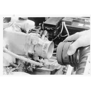
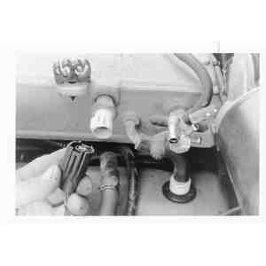
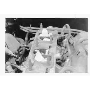
| Fig. 2: Linkage and hose location on the 2.3L engine
|
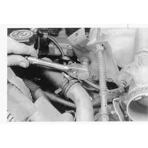
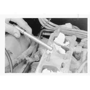
| Fig. 3: Disconnect the EGR valve supply tube
|
- Tag and disconnect the vacuum lines at the upper intake manifold vacuum
tree, at the EGR valve and at the fuel pressure regulator and canister purge
line as necessary.
- Remove the throttle linkage shield and disconnect the throttle linkage and
speed control cable (if equipped). Unbolt the accelerator cable from the bracket
and position the cable out of the way.
- Disconnect the air intake hose, air bypass hose and crankcase vent hose.
- Disconnect the PCV hose from the fitting on the underside of the upper intake
manifold.
- Loosen the clamp on the coolant bypass line at the lower intake manifold
and disconnect the hose.
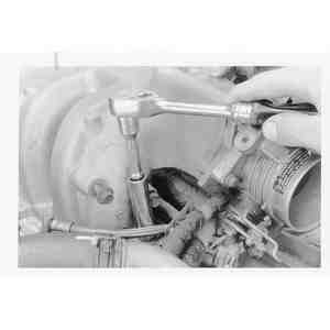
- Disconnect the EGR tube from the EGR valve by removing the flange nut.
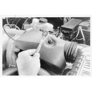
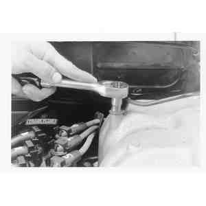
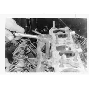
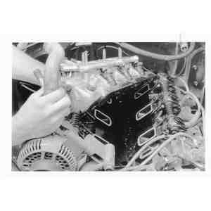
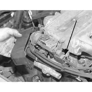
| Fig. 4: Upper intake manifold removal on the 2.3L
engine
|
- Remove the upper intake manifold retaining nuts. Remove the upper intake
manifold and throttle body assembly.
NOTE: If you only need to remove the upper intake manifold,
stop at this point. Otherwise, continue with the procedure to also remove
the lower intake manifold.
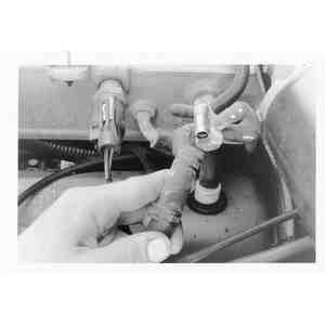
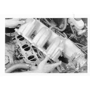
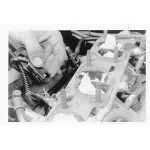
| Fig. 5: Fuel supply manifold and connections on the
2.3L engine. The injectors do not need to be removed unless a new
manifold is being installed
|
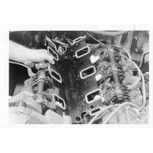
| Fig. 6: Lower intake manifold removal on the 2.3L
engine
|
- Disengage the push connect fitting at the fuel supply manifold and fuel
return lines. Disconnect the fuel return line from the fuel supply manifold.
- Remove the engine oil dipstick bracket retaining bolt.
- Unplug the electrical connectors from all four fuel injectors and move the
harness aside.
- Remove the four bottom retaining bolts from the lower manifold. The front
two bolts also secure an engine lifting bracket. Once the bolts are removed,
remove the lower intake manifold.
- Clean and inspect the mounting faces of the lower intake manifold and cylinder
head. Both surfaces must be clean and flat. If the intake manifold upper or
lower section is being replaced, it will be necessary to transfer components
from the old to the new part.
To install:
- To install, first clean and oil the manifold bolt threads. Install a new
lower manifold gasket.
- Position the lower manifold assembly to the head and install the engine
lifting bracket. Install the four top manifold retaining bolts finger-tight.
Install the four remaining manifold bolts and tighten to 12–15 ft. lbs.
(single plug 2.3L engines) or 15–22 ft. lbs. (2.3L twin plug engines),
following the sequence illustrated.
| Fig. 7: Lower intake manifold torque sequence on
the 2.3L engine

|
| Fig. 8: Upper intake manifold torque sequence on
the 2.3L engine
|
- Engage the four electrical connectors to the injectors.
- Install the engine oil dipstick, then connect the fuel return and supply
lines to the fuel supply manifold.
NOTE: The following procedures are for installing the upper
intake manifold.
- Make sure the gasket surfaces of the upper and lower intake manifolds are
clean. Place a gasket on the lower intake manifold assembly, then place the
upper intake manifold in position.
- Install the retaining bolts and tighten in sequence to 15–22 ft. lbs.
- Connect the EGR tube to the EGR valve and tighten it to 18 ft. lbs.
- Connect the coolant bypass line and tighten the clamp. Connect the PCV system
hose to the fitting on the underside of the upper intake manifold.
- If removed, install the vacuum tee on the upper intake manifold. Use Teflon® tape
on the threads and tighten to 12–18 ft. lbs. Reconnect the vacuum lines
to the tee, the EGR valve and the fuel pressure regulator and canister purge
line as necessary.
- Hold the accelerator cable bracket in position on the upper intake manifold
and install the retaining bolt. Tighten the bolt to 10–15 ft. lbs.
- Install the accelerator cable to the bracket.
- Position a new gasket on the fuel charging assembly air throttle body mounting
flange. Install the air throttle body to the fuel charging assembly. Install
two retaining nuts and two bolts and tighten to 15–25 ft. lbs.
- Connect the accelerator and speed control cable (if equipped), then install
the throttle linkage shield.
- Reconnect any electrical harness plugs which were removed.
- Connect the air intake hose, air bypass hose and crankcase ventilation hose.
- Reconnect the negative battery cable. Refill the cooling system to specifications
and pressurize the fuel system by turning the ignition switch on and off (without
starting the engine) at least six times. Leaving the ignition on for at least
five seconds each time.
- Start the engine and let it idle while checking for fuel, coolant and vacuum
leaks. Correct as necessary. Road test the vehicle for proper operation.
- Make sure the ignition is off, then drain the coolant from the radiator
(engine cold).
CAUTION
When draining the coolant, keep in mind that cats and dogs are attracted
by ethylene glycol antifreeze, and are quite likely to drink any that is
left in an uncovered container or in puddles on the ground. This will prove
fatal in sufficient quantity. Always drain the coolant into a sealable container.
Coolant should be reused unless it is contaminated or several years old.
- Disconnect battery negative cable.
- Release the fuel system pressure.
- Remove the accessory drive belt.
- Loosen the mounting bolt and remove the oil level dipstick and tube assembly.
- Label and unplug any electrical connectors related to the intake manifold
assemblies being removed.
- Remove air cleaner air intake duct from throttle body.
- Remove the throttle control splash shield.
- Disconnect throttle cable, cruise control cable (if equipped) and bracket
assembly.
- Label and disconnect all vacuum hoses from fittings on upper intake manifold.
- Disconnect the heater water hose from the intake manifold and the heater
line on the vehicle.
- Disconnect EGR tube at EGR valve and loosen the fitting on the exhaust manifold.
- Remove the EGR valve.
- Remove the EVAP emissions tube.
- Loosen the the 7 mounting bolts and remove the upper intake manifold. Remove
and discard the sealing gasket.
NOTE: If you only need to remove the upper intake manifold,
stop at this point. Otherwise, continue with the procedure to also remove
the lower intake manifold.
- Remove the A/C compressor from the mounting bracket and move off to the
side. Do not disconnect any A/C hoses.
- Loosen the 3 mounting bolts and one stud, then remove the A/C compressor
mounting bracket.
| Fig. 9: Remove the dash panel ground cable from the
intake manifold stud.
|
- Remove the dash panel ground cable from the intake manifold stud.
- Disengage the wiring harness connector from the retainer on the lower intake
manifold.
- Disconnect the fuel line spring lock coupling.
- Unplug the fuel injector wiring harness connectors.
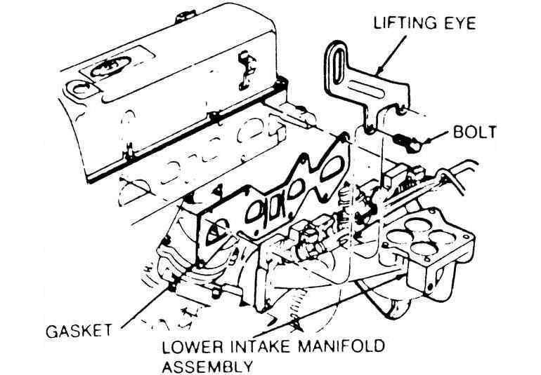
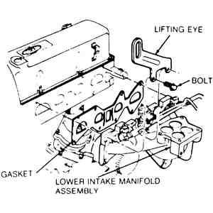
- Loosen the mounting nut and bolt, then remove the engine lifting eye.
- Remove intake manifold attaching bolts. Note length of manifold attaching
bolts during removal so that they may be installed in their original positions.
Tap manifold lightly with a plastic mallet to break gasket seal. Lift off
manifold.
- Remove all old gasket material and sealing compound.
To install:
- Apply sealing compound to the joining surfaces. Place the intake manifold
gasket in position.
| Fig. 10: Lower intake manifold tightening sequence
and procedure for the 2.5L engine

|
- Apply sealing compound to the attaching bolt bosses on the lower intake
manifold and position the intake manifold. Follow the tightening sequence
and tighten the bolts in 2 stages to the following specifications:
- Stage 1: 45–89 inch lbs. (7–10 Nm)
- Stage 2: 19–28 ft. lbs. (26–38 Nm)
- Place the engine lifting eye into position on the engine, then install and
tighten the mounting nut and bolt.
- Plug in the fuel injector wiring harness connectors.
- Connect the fuel line to the fuel rail, engaging the spring lock coupling.
- Engage the wiring harness connector to the retainer on the lower intake
manifold.
- Attach the dash panel ground cable to the intake manifold stud.
- Install the A/C compressor mounting bracket and tighten the 3 mounting bolts
and one stud.
- Place the A/C compressor onto the bracket and tighten the mounting fasteners.
| Fig. 11: Upper intake manifold tightening sequence
and procedure for the 2.5L engine
|
NOTE: The following procedures are for installing the upper
intake manifold.
- Mount the upper-to-lower intake manifold sealing gasket and install the
upper intake manidfold. Follow the tightening sequence and tighten the 7 bolts
in 2 stages to the following specifications:
- Stage 1: 45–89 inch lbs. (7–10 Nm)
- Stage 2: 19–28 ft. lbs. (26–38 Nm)
- Install the EVAP emissions tube.
- Install the EGR valve. Connect the EGR tube to the EGR valve, then tighten
the fitting to the exhaust manifold.
- Connect the heater water hose to the intake manifold and the heater line
on the vehicle. Tighten the hose clamps.
- Connect all vacuum hoses to the fittings on upper intake manifold.
- Connect throttle cable, cruise control cable (if equipped) and bracket assembly.
- Install the throttle control splash shield.
- Install the air cleaner air intake duct to the throttle body.
- Plug in any electrical connectors related to the removal of the intake manifold
assembly.
- Install the oil level dipstick/tube assembly and tighten the mounting bolt.
- Install the accessory drive belt.
- Connect battery negative cable.
- Refill and bleed the cooling system.
- Run engine at fast idle and check for coolant and oil leaks.
NOTE: The throttle body on 1994–97 B Series Pick-up is
cast integral to the upper intake manifold. To remove the upper intake manifold,
refer to Section 5 for throttle body removal.
- Drain the cooling system (with the engine cold).
CAUTION
When draining the coolant, keep in mind that cats and dogs are attracted
by ethylene glycol antifreeze, and are quite likely to drink any that is
left in an uncovered container or in puddles on the ground. This will prove
fatal in sufficient quantity. Always drain the coolant into a sealable container.
Coolant should be reused unless it is contaminated or several years old.
- Disconnect the battery ground cable.
- Depressurize the fuel system and remove the air intake throttle body (1994–97)
or throttle body (1998) as outlined in Section 5.
- On 1998 B Series Pick-up, remove the upper intake manifold.
- Disconnect the fuel return and supply lines.
- Remove the fuel injector wiring harness from the engine.
- Disconnect the upper radiator hose.
- Disconnect the water outlet heater hose.
- If equipped with distributor ignition, disconnect the distributor cap with
the spark plug wires attached. Matchmark and remove the distributor assembly.
- If equipped with distributorless ignition, Label and remove the spark plug
wires from the coil pack, then remove the coil pack.
- Remove the valve covers.
- Remove the rocker arms and pushrods.
- Remove the intake manifold attaching bolts and studs (Torx® socket
required).
- Lift the intake manifold off the engine. Use a plastic mallet to tap lightly
around the intake manifold to break it loose, if necessary. Do not pry between
the manifold and cylinder head with any sharp instrument. The manifold can
be removed with the fuel rails and injectors in place.
- Remove the manifold side gaskets and end seals and discard. If the manifold
is being replaced, transfer the fuel injector and fuel rail components to
the new manifold on a clean workbench. Clean all gasket mating surfaces.
To install:
- First lightly oil all attaching bolts and stud threads. The intake manifold,
cylinder head and cylinder block mating surfaces should be clean and free
of old silicone rubber sealer. Use a suitable solvent to clean these areas.
| Fig. 12: Silicone sealer and intake end seal application
for the 3.0L engine
|
| Fig. 13: Intake manifold gasket positioning for the
3.0L
|
| Fig. 14: Intake manifold torque sequence for the
3.0L
|
- Apply silicone rubber sealer (D6AZ–19562–A or equivalent) to
the intersection of the cylinder block assembly and head assembly at four
corners as illustrated.
NOTE: When using silicone rubber sealer, assembly must
occur within 15 minutes after sealer application. After this time, the sealer
may start to set–up and its sealing effectiveness may be reduced.
In high temperature/humidity conditions, the RTV will start to skin over
in about 5 minutes.
- Install the front intake manifold seal and rear intake manifold seal, then
secure them with retaining features.
- Position the intake manifold gaskets in place and insert the locking tabs
over the tabs on the cylinder head gaskets.
- Apply silicone rubber sealer over the gasket in the same places as in Step
14.
- Carefully lower the intake manifold into position on the cylinder block
and cylinder heads to prevent smearing the silicone sealer and causing gasketing
voids.
- Install the retaining bolts. Tighten in two stages, using the sequence illustrated,
first to 11 ft. lbs., then to 18 ft. lbs.
- If installing a new manifold, install fuel supply rail and injectors. Refer
to the necessary service procedures.
- Install the pushrods and rocker arms. Apply oil to pushrod and fulcrum prior
to installation. Rotate the crankshaft to place the lifter on the heel position
or base circle of camshaft. Tighten to 8 ft. lbs. to seat fulcrum in cylinder
head. Final bolt torque is 24 ft. lbs.
- Install valve covers, fuel injector harness, throttle body assembly (1994–97)
or upper intake manifold and throttle body (1998), hose and electrical connections.
- If equipped with distributor ignition, install the distributor assembly,
using the matchmarks made earlier to insure correct alignment. Install the
distributor cap and spark plug wires.
- If equipped with distributorless ignition, install the coil pack then install
the spark plug wires to their original locations.
- Install coolant hoses. Connect all vacuum lines. Reconnect fuel lines. Install
fuel line safety clips.
- Fill and bleed cooling system. If any engine coolant accidentally spilled
into the engine while the intake was off, change engine oil and filter.
- Install air cleaner hose. Connect battery ground cable. Start engine and
check for coolant, oil, fuel and vacuum leaks.
- If equipped with distributor ignition, verify base initial timing as outlined.
Check and adjust engine idle as necessary.
The intake manifold is a 4–piece assembly, consisting of the upper intake
manifold, the throttle body, the fuel supply manifold, and the lower intake
manifold.
- Disconnect the battery ground cable.
| Fig. 15: Begin the intake removal by unbolting the
throttle linkage weather shield . . .
|
| Fig. 16: . . . then remove the air intake duct from
the throttle body
|
| Fig. 17: Disconnect the throttle linkage, then unbolt
and remove the cable bracket
|
- Remove the weather shield.
- Remove the air cleaner intake duct.
- Disconnect the throttle cable and bracket.
| Fig. 18: Label all of the electrical and vacuum connections
on the intake manifold . . .

|
| Fig. 19: . . . then disconnect the vacuum lines .
. .
|
| Fig. 20: . . . and the electrical harness plugs
|
- Tag and unplug all vacuum lines connected to the manifold.
- Tag and disconnect all electrical wires attached to the upper manifold assembly.
- Relieve the fuel system pressure.
| Fig. 21: Also, ensure that any brackets which are
bolted to the manifold are unfastened
|
- Tag and remove the spark plug wires.
- Remove the EDIS ignition coil and bracket.
| Fig. 22: Remove the upper intake manifold attaching
bolts . . .
|
| Fig. 23: . . . then lift the manifold from the engine
|
| Fig. 24: Stuff rags into the intake runners, then
remove the old upper intake gasket; use care when scraping
|
- Remove the 6 attaching nuts and lift off the upper manifold.
NOTE: If you only need to remove the upper intake manifold,
stop at this point. Otherwise, continue with the procedure to also remove
the lower intake manifold.
| Fig. 25: Disconnect the fuel supply and return lines
from the injector fuel rail

|
| Fig. 26: Label all of the electrical connections
on the lower intake manifold . . .
|
| Fig. 27: . . . then disconnect them. Next, remove
the valve covers
|
- Disconnect the fuel supply and return lines from the injector fuel rail.
- Label and disconnect all of the electrical connections on the lower manifold
assembly.
- Remove the valve covers.
| Fig. 28: Remove the lower intake manifold attaching
bolts . . .
|
| Fig. 29: . . . then lift the manifold from the engine
|
- Remove the lower intake manifold bolts. Tap the manifold lightly with a
plastic mallet and remove it.
| Fig. 30: Remove the old intake gasket from the cylinder
heads and engine block
|
- Clean all surfaces of old gasket material.
To install:
- Apply RTV silicone gasket material at the junction points of the heads and
manifold.
NOTE: This material will set within 15 minutes, so work
quickly!
- Install new manifold gaskets and again apply the RTV material.
| Fig. 31: Intake manifold and gasket installation
for the 4.0L
|
| Fig. 32: Intake manifold torque sequence for the
4.0L
|
- Position the manifold and install the nuts hand-tight. Tighten the nuts
in 4 stages, using the sequence shown, as follows:
- Stage 1: 22 inch lbs. (3 Nm)
- Stage 2: 88 inch lbs. (10 Nm)
- Stage 3: 115 inch lbs. (13 Nm)
- Stage 4: 11–13 ft. lbs. (14–18 Nm)
- Once again, apply RTV material to the manifold/head joints.
- Install the valve covers using new gaskets.
NOTE: The following procedures are for installing the upper
intake manifold.
- Position a new gasket and install the upper manifold. Tighten the nuts to
15–18 ft. lbs. (20–25 Nm).
- Install the EDIS coil.
- Connect the fuel and return lines.
- Install the throttle body.
- Connect all wires.
- Connect all vacuum lines.
- Connect the throttle linkage.
- Install the weather shield.
- Install the air cleaner and duct.
- Fill and bleed the cooling system.
- Connect the battery ground.
- Run the engine and check for leaks.
- Relieve the fuel system pressure and disconnect the negative battery cable.
Drain the cooling system.
- Disconnect the air intake tube and ventilation hose. Remove the air pipe
and resonance chamber.
- Disconnect the accelerator cable and coolant hoses. Tag and disconnect the
electrical connectors to the solenoid valve, throttle sensor and idle switch.
- Remove the throttle body.
- Remove the upper intake manifold brackets.
- Tag and disconnect the vacuum hoses and PCV hose. Tag and disconnect the
intake air thermosensor connector and ground wire.
- Remove the injector harness bracket and remove the upper intake manifold.
- Tag and disconnect the vacuum hoses from the lower intake manifold. Disconnect
the fuel lines.
- Remove the fuel supply manifold and the injectors. Remove the injector harness
and bracket.
- Remove the pulsation damper and the intake manifold bracket. Remove the
attaching nuts and remove the lower intake manifold.
To install:
- Clean all gasket mating surfaces.
- Position a new intake manifold-to-cylinder head gasket and install the lower
intake manifold. Tighten the nuts to 14–19 ft. lbs. (19–25 Nm).
- Install the intake manifold bracket and pulsation damper. Install the injector
harness and bracket. Tighten the pulsation damper and injector harness bracket
bolts to 69–95 inch lbs. (7.8–11.0 Nm).
- Install the injectors and the fuel supply manifold. Tighten the fuel supply
manifold attaching bolts and tighten to 14–19 ft. lbs. (19–25
Nm).
- Connect the fuel lines. Connect the vacuum hoses to the lower intake manifold.
- Position a new gasket and install the upper intake manifold. Tighten the
attaching bolts/nuts to 14–19 ft. lbs. (19–25 Nm).
- Install the injector harness bracket. Connect the ground wire and air thermosensor
electrical connector. Connect the PCV hose and the vacuum hoses to the upper
intake manifold.
- Install the upper intake manifold brackets.
- Position a new gasket and install the throttle body. Tighten the mounting
nuts to 14–19 ft. lbs. (19–25 Nm).
- Connect the electrical connectors at the idle switch, throttle sensor and
solenoid valve.
- Connect the coolant hoses and the accelerator cable. Install the air pipe
and resonance chamber.
- Connect the ventilation hose and air intake hose. Connect the negative battery
cable.
- Fill and bleed the cooling system. Run the engine and check for leaks and
proper operation.
| Fig. 33: Upper engine assembly — 2.6L
engines
|
CAUTION
Fuel injection systems remain under pressure after the engine has been turned
OFF. Properly relieve fuel pressure before disconnecting any fuel lines. Failure
to do so may result in fire or personal injury. Do not allow fuel spray or fuel
vapors to come in contact with a spark or open flame. Keep a dry chemical fire
extinguisher nearby. Never store fuel in an open container due to risk of fire
or explosion.
- Relieve the fuel system pressure, and disconnect the negative battery cable.
Drain the cooling system.
- Remove the air intake tube from the throttle body. Disconnect the accelerator
cable.
- Disconnect the throttle sensor connector and the coolant hoses. Remove the
throttle body.
- Tag and disconnect the vacuum hoses. Remove the bypass air control valve
and the intake air pipe.
| Fig. 34: Remove the front cover from the dynamic
chamber and discontinue the electrical connector to the shutter valve
actuator before removing the dynamic chamber
|
- Remove the extension manifolds. Remove the dynamic chamber (upper intake
plenum) with the shutter valve actuator.
- Remove the fuel supply manifold and the injectors. Disconnect the coolant
hoses.
- Loosen the lower intake manifold nuts, in sequence, in 2 steps, then remove
the lower intake manifold.
To install:
- Clean all gasket mating surfaces.
- Position new lower intake manifold gaskets, and install the lower intake
manifold.
- Install the intake manifold washers with the white paint mark upward. Install
the nuts and tighten, in sequence, in 2 steps to a maximum torque of 14–19
ft. lbs. (19–25 Nm).
| Fig. 35: Intake manifold tightening sequence — 3.0L
engine 1994–95
|
- Install the injectors and the fuel supply manifold. Tighten the attaching
bolts to 14–19 ft. lbs. (19–25 Nm).
- Connect the coolant hoses.
- Install a new O-ring on the lower intake manifold and install the upper
intake plenum. Apply clean engine oil to new O-rings and install on the extension
manifolds. Position new gaskets and install the extension manifolds. Tighten
the attaching nuts to 14–19 ft. lbs. (19–25 Nm).
- Position a new gasket and install the intake air pipe. Install the bypass
air control valve. Tighten the attaching bolts/nuts to 14–19 ft. lbs.
(19–25 Nm).
- Position a new gasket and install the throttle body. Tighten the attaching
nuts to 14–19 ft. lbs. (19–25 Nm).
- Connect the coolant and vacuum hoses. Connect the throttle sensor connector
and accelerator cable.
- Adjust the accelerator cable deflection to 0.039–0.118 inch (1–3mm).
- Connect the air intake tube and the negative battery cable.
- Fill and bleed the cooling system. Run the engine and check for leaks and
proper operation.
| Fig. 36: Intake air system — 3.0L engine
1996–98
|
CAUTION
Fuel injection systems remain under pressure after the engine has been turned
OFF. Properly relieve fuel pressure before disconnecting any fuel lines. Failure
to do so may result in fire or personal injury. Do not allow fuel spray or fuel
vapors to come in contact with a spark or open flame. Keep a dry chemical fire
extinguisher nearby. Never store fuel in an open container due to risk of fire
or explosion.
- Relieve the fuel system pressure, and disconnect the negative battery cable.
Drain the cooling system.
- Remove the clamps and remove the air intake hose from the throttle body
and the MAF sensor.
- Disconnect the accelerator cable and if equipped, the cruise control cable.
- Disconnect the throttle position sensor connector.
- Remove the 2 bolts and the 2 nuts and remove the throttle body unit and
gasket.
- Disconnect the hoses and connector and remove the BAC valve.
- Remove the VRIS solenoid valve.
- Remove the PRC solenoid valve No. 1 and the PRC solenoid valve No. 2.
- Remove the 2 bolts and the 2 nuts and remove the VRIS shutter valve actuator
and the gasket.
- Remove the mounting bolts and the dynamic chamber.
- Disconnect the fuel delivery pipe from the fuel distributor. Disconnect
the fuel injector connectors, remove the mounting nuts and remove the fuel
distributor with the injectors.
- Remove the water hoses from the water outlet and remove the water outlet.
- Disconnect any water hoses and vacuum hoses from the intake manifold. Remove
the mounting nuts, washers, and remove the intake manifold and gaskets.
To install:
| Fig. 37: Intake manifold gasket installation — 3.0L
engine 1996–98
|
NOTE: Face the bead of the intake manifold gasket toward
the intake manifold.
- Install the intake manifold with 2 new gaskets, the mounting washers and
nuts. Hint: install the manifold washers with the white paint marks facing
up. Torque the mounting nuts to 14–18 ft. lbs. (19–25 Nm).
| Fig. 38: Intake manifold tightening sequence and
mounting washers — 3.0L engine 1996–98
|
- Reinstall any water hoses and vacuum hoses to the intake manifold and reclamp.
- Install the water outlet to the intake manifold with a new gasket. Torque
the mounting nuts to 14–18 ft. lbs. (19–25 Nm). Reinstall the
water hoses with the clamps.
- Reinstall the fuel delivery pipe with the injectors and torque the mounting
nuts to 14–18 ft. lbs. (19–25 Nm). Reconnect the fuel delivery
pipe and reconnect the fuel injector connectors.
| Fig. 39: Dynamic chamber gasket installation — 3.0L
engine 1996–98
|
NOTE: Face the bead of the dynamic chamber gasket toward
the dynamic chamber.
- Install the dynamic chamber with a new gasket. Torque the mounting bolts
to 70–95.4 inch lbs. (7.9–10.7 Nm).
- Install the VRIS shutter valve actuator with a new gasket and the 2 nuts
and 2 bolts. Torque the bolts and nuts to 70–95.4 inch lbs. (7.9–10.7
Nm).
- Install the PRC solenoid valve No. 2 and the PRC solenoid valve No. 1.
- Reinstall the VRIS solenoid and connect the connectors.
- Install the BAC valve with a new gasket. Torque the 2 mounting bolts and
the 2 nuts to 70–95.4 inch lbs. (7.9–10.7 Nm). Reconnect the hoses
and connector.
- Using a new gasket, install the throttle body assembly with the 2 bolts
and the 2 nuts. Torque the bolts and nuts to 14–16 ft. lbs. (19–25
Nm).
- Reconnect the throttle position sensor connector.
- Reconnect the accelerator cable and if equipped, the cruise control cable.
- Install the air intake hose to the throttle body assembly and the MAF sensor
with the 2 clamps.
- Refill the cooling system, reconnect the negative battery cable, start the
engine and operate until normal temperature, check for coolant leaks, and
proper operation.