Previous Next

Rocker Arms/Shafts

REMOVAL & INSTALLATION

2.3L/2.5L Engines (B Series Pick-up)

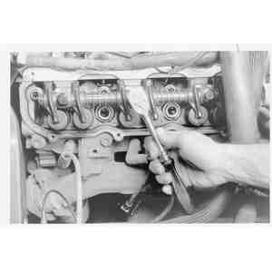
NOTE: A special tool is required to compress the valve spring.

  1. Remove the valve cover and associated parts as required.
  2. Rotate the camshaft so that the base circle of the cam is against the cam follower you intend to remove.

    Fig. 1: Use a special valve spring compressing tool to remove the follower

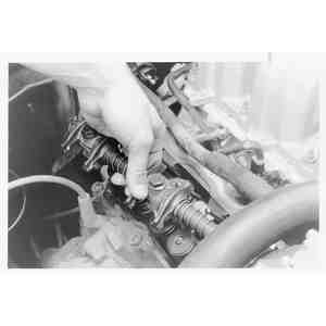
    NOTE: If removing more than one cam follower, label them so they can be returned to their original position.

  3. Using special tool 49-UN01-135 or equivalent, depress the valve spring, as necessary, and slide the cam follower over the lash adjuster and out from under the camshaft.
  4. Install the cam follower in the reverse order of removal. Lubricate the followers with SAE 50W engine oil meeting current API specification prior to installing.
2.6L Engine (MPV)
  1. Disconnect the negative battery cable.
  2. Remove the air intake hose.
  3. Remove the rocker arm cover.

    Fig. 2: Rocker arm/shaft assembly mounting bolt removal sequence — Reverse the sequence for installation

  4. Loosen the rocker arm/shaft assembly mounting bolts in 2–3 steps in the proper sequence. Remove the rocker arm/shaft assembly together with the bolts.
  5. If necessary, disassemble the rocker arm/shaft assembly, noting the position of each component to ease reassembly.
  6. Check for wear or damage to the contact surfaces of the shafts and rocker arms; replace as necessary.

    Fig. 3: Measuring the rocker arm inside diameter

    Fig. 4: Measuring the rocker arm shaft diameter

  7. Measure the rocker arm inner diameter, it should be 0.8268–0.8281 in. (21.000–21.033mm). Measure the rocker arm shaft diameter, it should be 0.8252–0.8260 in. (20.959–20.980mm).
  8. Subtract the shaft diameter from the rocker arm diameter to get the oil clearance. The oil clearance should be 0.0008–0.0029 in. (0.020–0.074mm) and should not exceed 0.004 in. (0.10mm). Replace parts, as necessary, if the oil clearance is not within specification.

    To install:

  9. Apply clean engine oil to the rocker arm shafts and rocker arms and assemble the rocker arm/shaft assembly in the reverse order of disassembly, noting the following:
    1. The intake side shaft has twice as many oil holes as the exhaust side shaft.
    2. The No. 4 camshaft cap has an oil hole from the cylinder head; make sure it is installed correctly.
  10. Apply clean engine oil to the camshaft journals and valve stem tips.
  11. Install the rocker arm/shaft assembly and tighten the mounting bolts, in sequence, in 2–3 steps to a maximum torque of 14–19 ft. lbs. (19–25 Nm).
  12. Coat a new gasket with silicone sealer and install on the rocker arm cover. Apply sealer to the cylinder head in the area of the half circle seals and install the rocker arm cover. Install the mounting bolts and tighten to 52–78 inch lbs. (5.9–8.8 Nm).
  13. Install the air intake hose. Connect the negative battery cable, start the engine and check for leaks and proper operation.
3.0L Engines (B Series Pick-up)
  1. Remove the rocker arm covers.
  2. Remove the single retaining bolt at each rocker arm.

    Fig. 5: Exploded view of the valve rocker arms used on the 3.0L engines

  3. The rocker arm and pushrod may then be removed from the engine. Keep all rocker arms and pushrods in order so they may be installed in their original locations.
  4. Installation is the reverse of removal. Lubricate the rocker arm assemblies with SAE 50W engine oil. Insure that the fulcrums are properly seated into the cylinder head. Tighten the rocker arm fulcrum bolts to 18–28 ft. lbs. (24–38 Nm).
3.0L Engine (MPV)
  1. Disconnect the negative battery cable.
  2. If removing the driver's side rocker arm/shaft assembly, proceed as follows:
    1. Remove the air inlet tube.
    2. Tag and disconnect the necessary electrical connectors and vacuum hoses from the throttle body and intake air pipe.
    3. Disconnect the throttle cable.
    4. Remove the throttle body and intake air pipe.
  3. Remove the rocker arm cover.

    Fig. 6: Rocker arm/shaft assembly mounting bolt removal sequence — Reverse the sequence for installation

  4. Loosen the rocker arm and shaft assembly mounting bolts in sequence, in 2–3 steps. Remove the assembly with the bolts.
  5. If necessary, disassemble the rocker arm/shaft assembly, noting the position of each component to ease reassembly.
  6. Remove the valve lifter (Hydraulic Lash Adjuster — HLA) and inspect it. Replace the HLA as necessary.
  7. Check for wear or damage to the contact surfaces of the shafts and rocker arms; replace as necessary.
  8. Measure the rocker arm inner diameter, it should be 0.7480–0.7493 in. (19.000–19.033mm). Measure the rocker arm shaft diameter, it should be 0.7464–0.7472 in. (18.959–18.980mm).
  9. Subtract the shaft diameter from the rocker arm diameter to get the oil clearance. The oil clearance should be 0.0008–0.0029 in. (0.020–0.074mm) and should not exceed 0.004 in. (0.10mm). Replace parts, as necessary, if the oil clearance is not within specification.

    To install:

  10. To install the HLA, pour engine oil into the rocker arm oil reservoir. Apply engine oil to the HLA, and carefully install the HLA into the rocker arm.
  11. Apply clean engine oil to the rocker arm shafts and rocker arms and assemble the rocker arm/shaft assembly. The intake side shaft has twice as many oil holes as the exhaust side shaft.
  12. Apply clean engine oil to the camshaft journals and valve stem tips.
  13. Install the rocker arm/shaft assembly and tighten the mounting bolts, in sequence, in 2–3 steps to a maximum torque of 14–19 ft. lbs. (19–25 Nm).

    NOTE: Be careful that the rocker arm shaft spring does not get caught between the shaft and mounting boss during installation.

  14. Coat a new gasket with silicone sealant and install on the rocker arm cover. Install the rocker arm cover with new seal washers and tighten the bolts to 30–39 inch lbs. (3.4–4.4 Nm).
  15. Install the intake air pipe, throttle body and air intake tube, if removed. Connect the throttle cable and the necessary electrical connectors and vacuum hoses.
  16. Connect the negative battery cable, start the engine and check for leaks and proper operation.
4.0L Engine (Navajo and B Series Pick-up)
  1. Remove the valve rocker arm covers.
  2. Remove the rocker arm shaft stand attaching bolts by loosening the bolts two turns at a time, in sequence (from the end of shaft to middle shaft).
  3. Lift off the rocker arm and shaft assembly. If equipped, remove the oil baffle.

    Fig. 7: To remove the rocker shaft, first remove the valve cover, then loosen the shaft retaining bolts . . .

    Fig. 8: . . . and remove the assembly from the cylinder head

    To install:

  4. If equipped, loosen the valve lash adjusting screws a few turns. Apply engine oil to the assembly to provide the initial lubrication.

    Fig. 9: Rocker arm shaft installation on the 4.0L engine

  5. If equipped, install the oil baffle.
  6. Install rocker arm shaft assembly to the cylinder head and guide adjusting screws on to the pushrods.
  7. Install and tighten rocker arm stand attaching bolts to specification, two turns at a time, in sequence (from middle of shaft to the end of shaft).
  8. Adjust the valve lash to the cold specified setting. Refer to Section 1 under Valve Lash Adjustment for procedures.
  9. Install the valve rocker arm covers.
DISASSEMBLY & REASSEMBLY
  1. Remove the spring washer and pin from each end of the valve rocker arm shaft.
  2. Slide the rocker arms, springs and rocker arm shaft supports off the shaft. Be sure to mark the parts for re–assembly in the same locations.
  3. If it is necessary to remove the plugs from each end of the shaft, drill or pierce the plug on one end. Use a steel rod to knock out the plug on the opposite end. Working from the open end, knock out the remaining plug.
  4. The oil holes in the rocker arm shaft must point down when the shaft is installed. This position of the shaft can be recognized by a notch on the front face of the shaft.
  5. If the plugs were removed from the shaft, use a blunt tool and install a plug, cup side out, in each end of the shaft.
  6. Install a spring washer and pin on one end of the shaft, coat the rocker arm shaft with heavy engine oil and install the parts in the same sequence they were removed.

Previous Next