Previous Next

Timing Belt and Sprockets

2.3L/2.5L Engines

Fig. 12: Timing belt assembly on the 2.3L engine

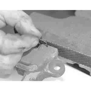
Fig. 13: Releasing the timing belt tensioner using a special tool

  1. Disconnect the negative battery cable.
  2. Rotate the engine so that No. 1 cylinder is at TDC on the compression stroke. Check that the timing marks are aligned on the camshaft and crankshaft pulleys. An access plug is provided in the cam belt cover so that the camshaft timing can be checked without removal of the cover or any other parts. Set the crankshaft to TDC by aligning the timing mark on the crank pulley with the TDC mark on the belt cover. Look through the access hole in the belt cover to make sure that the timing mark on the cam drive sprocket is lined up with the pointer on the inner belt cover.

    NOTE: Always turn the engine in the normal direction of rotation. Backward rotation may cause the timing belt to jump time, due to the arrangement of the belt tensioner.

  3. Remove the timing belt cover.
  4. Loosen the belt tensioner pulley assembly, then position a camshaft belt adjuster tool (T74P–6254–A or equivalent) on the tension spring rollpin and retract the belt tensioner away from the timing belt. Tighten the adjustment bolt to lock the tensioner in the retracted position.
  5. Remove the timing belt.

    To install:

  6. Install the new belt over the crankshaft sprocket and then counterclockwise over the auxiliary and camshaft sprockets, making sure the lugs on the belt properly engage the sprocket teeth on the pulleys. Be careful not to rotate the pulleys when installing the belt.
  7. Release the timing belt tensioner pulley, allowing the tensioner to take up the belt slack. If the spring does not have enough tension to move the roller against the belt (belt hangs loose), it might be necessary to manually push the roller against the belt and tighten the bolt.

    NOTE: The spring cannot be used to set belt tension; a wrench must be used on the tensioner assembly.

  8. Rotate the crankshaft two complete turns by hand (in the normal direction of rotation) to remove the slack from the belt, then tighten the tensioner adjustment and pivot bolts to specifications. Refer to the necessary illustrations. Make sure the belt is seated properly on the pulleys and that the timing marks are still in alignment when No. 1 cylinder is again at TDC/compression.
  9. Install the crankshaft pulley and belt guide.
  10. Install the timing belt cover.
  11. Connect the negative battery cable.
  12. Start the engine and check the engine performance. Make any necessary adjustments.
3.0L Engine (MPV)

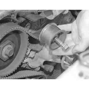
Fig. 14: Remove the upper idler pulley

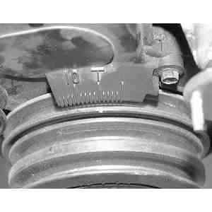
Fig. 15: Location of the timing marks on the timing belt cover

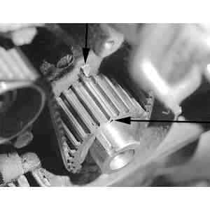
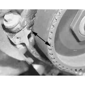
Fig. 16: Before removing the timing belt, line up the timing marks on the crankshaft sprocket and the engine block . . .

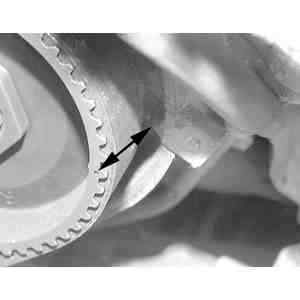
Fig. 17: . . . the right side camshaft sprocket and the mark on the cylinder head . . .

Fig. 18: . . . and the left side camshaft sprocket and the cylinder head

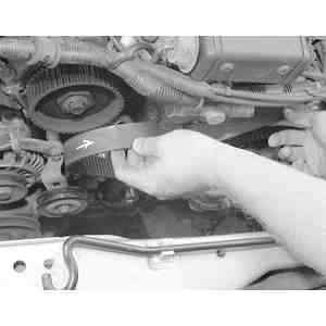
Fig. 19: Mark the direction of rotation on the timing belt if installing the same belt

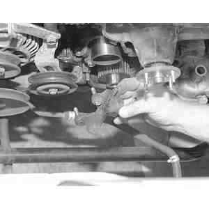
Fig. 20: Rmove the timing belt

Fig. 21: Remove the timing belt tensioner from the front of the engine

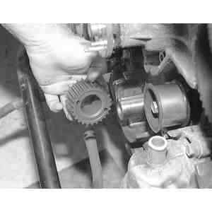
Fig. 22: Remove the cranshaft sprocket by pulling straight off of the crankshaft

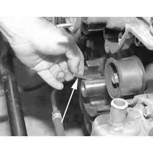
Fig. 23: After removing the crankshaft sprocket, remove the woodruff ke. Be careful not to lose this

  1. Disconnect the negative battery cable, and drain the cooling system.
  2. Remove the timing belt covers.
  3. Remove the upper idler pulley.
  4. Turn the crankshaft to align the matching marks on the sprockets. If the timing belt is to be reused, make an arrow on the belt to indicate rotation direction.
  5. Remove the timing belt and automatic tensioner.
  6. Using SST 49 H012 010 tool or its equivalent, loosen and remove the camshaft sprocket lock bolts. Remove the camshaft sprockets.
  7. Using a suitable puller, remove the crankshaft sprocket.

    To install:

  8. Install the crankshaft sprocket to the crankshaft.
  9. Install the camshaft sprockets with the lock bolts and torque the bolts to 52–59 ft. lbs. (71–80 Nm).

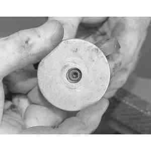
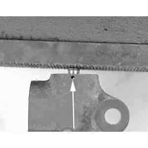
    Fig. 24: Place the washer on the tensioner allowing the plug on the tensioner to fit through the hole in the washer

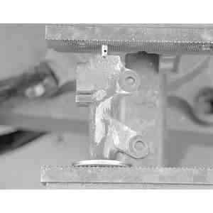
    Fig. 25: Mount the tensioner assembly and washer in the bench vise as shown

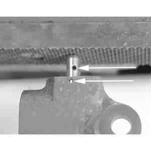
    Fig. 26: When compressing the tensioner and plunger, be sure to line up the holes of the plunger to the hole in the tensioner body

    Fig. 27: Once the plunger and tensioner holes are aligned . . .

    Fig. 28: . . . place a small hex key into the holes to keep the plunger compressed

  10. Set a plane washer at the bottom of the tensioner body to prevent damage to the body plug. Press in the tensioner rod slowly, using a press or a vise.

    NOTE: Do not press the tensioner rod more than 2200 lbs. (9800N).

  11. Insert a pin to hold the tensioner rod in the body. Install the automatic tensioner and tighten the mounting bolts to 14–19 ft. lbs. (19–25 Nm).
  12. Install the crankshaft pulley lock bolt and loosely tighten. Check the alignment of the matching marks on the sprockets.
  13. With the upper idler pulley removed, install the timing belt, making sure there is no slack between the crankshaft and camshaft sprockets. If the timing belt is being reused, it must be installed in the same direction of rotation.
  14. Install the upper idler pulley and tighten the attaching bolt to 27–38 ft. lbs. (37–52 Nm).
  15. Turn the crankshaft twice in the direction of rotation and align the matching marks. If the marks do not align, repeat the previous three steps.
  16. Remove the pin from the automatic tensioner. Turn the crankshaft twice and align the matching marks. Make sure the marks are aligned.
  17. Check the timing belt deflection. The deflection should be 0.20–0.28 in. (5–7mm). Do not apply tension other than that of the automatic tensioner.
  18. If the deflection is not correct, repeat the previous three steps.
  19. Remove the crankshaft pulley lock bolt.
  20. Install the timing belt cover, along with the related components.
  21. Reinstall the crankshaft pulley and torque the lock bolt to 116–123 ft. lbs. (37–52 Nm).
  22. Fill and bleed the cooling system.
  23. Run the engine and check for leaks and proper operation. Check the idle speed and the ignition timing.

Previous Next