NOTE: To service the valve cover on the 2.3L engine, the throttle
body assembly and EGR supply tube must first be removed. Refer to the necessary
service procedures.
- Disconnect the negative battery cable.
- Unplug any electrical connections on the air intake hose, then remove the
hose.
- Remove any splash shielding from around the throttle body.
- Remove the throttle body assembly from the intake manifold.
- Label and disconnect any electrical connections, including spark plug cables,
that will interfere with the removal of the valve cover.
- If necessary, remove the EGR supply tube.
- Remove the valve cover retaining bolts and remove the valve cover.
NOTE: A gentle tap with a soft hammer may help to break
the seal on the gasket.
WARNING
Never pry between the valve cover and the cylinder head. Damage to the machined
sealing surface, or distortion to the valve cover could occur, resulting
in an oil leak.
| Fig. 1: Exploded view of the 2.3L engine rocker arm
cover
|
- Remove the valve cover gasket from the cover.
To install:
- Thoroughly clean the gasket mating surfaces on the cover and the cylinder
head.
- Install a new gasket to the valve cover.
- Place the valve cover onto the cylinder head and install all of the retaining
bolts finger-tight.
- Alternately tighten the bolts to 62–97 inch lbs. (7–11 Nm).
- If removed, install the EGR supply tube.
- Install any electrical connections which were removed.
- Install the throttle body to the intake manifold.
- Install any splash shielding removed from around the throttle body.
- Install the air intake hose and attach the wire harness connections which
were removed.
- Reconnect the negative battery cable.
- Start the engine and check for leaks.
- Disconnect the negative battery cable.
- Disengage the wiring connector from the Intake Air Temperature (IAT) sensor.
- Remove the air cleaner duct assembly.
- Remove the accelerator control splash shield.
- Disconnect the accelerator cable.
- Disconnect the crankcase vent hose from the valve cover.
- Unplug the wiring harness connectors from the Idle Air Control (IAC) valve
and the Throttle Position Sensor (TPS).
- Label each spark plug wire prior to its removal in order to ease the installation
of the wires on the correct spark plugs. Remove the spark plug wires.
- Remove the exhaust side spark plug wire retainer from the studs on the valve
cover.
- Remove the throttle body.
- Remove the vacuum line from the EGR valve and intake.
- Remove the valve cover mounting bolts.
- Remove the valve cover. Remove and discard gasket.
| Fig. 2: Remove the 8 mounting bolts and lift the
valve cover off of the engine
|
To install:
- Clean all gasket material from the cylinder heads and rocker arm cover gasket
surfaces.
- Install a new gasket on the valve cover.
- Install the valve cover and mounting bolts. Tighten the mounting bolts to
80–115 inch lbs. (9–13 Nm).
- Connect the vacuum line to the EGR valve and intake.
- Install the throttle body.
- Install the exhaust side spark plug wire retainer onto the valve cover studs.
- Connect the spark plug wires.
- Plug in the wiring harness connectors to the IAC valve and TPS.
- Connect the crankcase vent hose to the valve cover.
- Connect the accelerator cable.
- Install the accelerator control splash shield.
- Install the air cleaner duct assembly.
- Attach the wiring connector to the IAT sensor.
- Connect the negative battery cable. Start the engine and check for oil leaks.
- Disconnect the battery ground cable.
- Disconnect the accelerator cable.
- Remove the air intake pipe and resonance chamber.
- Tag and disconnect any wires and hoses in the way.
- Unbolt and remove the cover.
- Thoroughly clean all mating surfaces of old gasket material and/or sealer.
The cover may use a gasket or RTV gasket sealer. If a gasket is used, coat
the new gasket with sealer and position it on the head. If RTV material is
used, squeeze a 1⁄8 inch
bead on the head sealing surface.
- Install the rocker cover. Torque the bolts to 5278 inch lbs. (6–9
Nm).
- Disconnect the air bypass valve cable.
- Loosen the clamps and remove the air intake crossover.
- Disconnect the PCV valve at the cover.
- Remove the retaining bolts and remove the cam cover.
| Fig. 3: Install the cam cover with a new gaskets
and seal wasers for the bolts
|
- To install the cover, first supply new gaskets and seal washers for the
bolts.
- Tighten the bolts in several stages, going back and forth across the cover
to 30–40 inch lbs. (3.5–4.5 Nm).
- Once all the associated components are installed, start the engine and allow
it to reach normal operating temperature. Check for oil leaks.
NOTE: The valve covers installed on the 3.0L engine incorporate
integral (built in) gaskets which should last the life of the vehicle. Replacement
gaskets are available if required.
- Disconnect the negative battery cable.
- Remove the air cleaner/inlet duct hose assembly.
- Remove the throttle body assembly.
- Label and disconnect any vacuum lines that are in the way.
- Remove the ignition coil pack, if equipped.
- Remove the upper intake manifold.
- If removing the right valve cover, perform the following steps:
- Disconnect the alternator wiring harness.
- Disconnect the closure hose from the valve cover.
- Disengage the engine harness connectors from the valve cover.
- Remove the fuel injector harness stand-offs from the inboard valve cover
studs and move them out of the way.
- Disconnect the PCV hose from the oil fill adapter.
- If removing the left valve cover, perform the following steps:
- Remove the PCV valve.
- Remove the fuel injector harness stand-offs from the inboard valve cover
studs and move them out of the way.
- Tag and remove the spark plug wires.
- Remove the spark plug wire separator assembly from the valve cover mounting
studs and move them out of the way.
- Remove the valve cover mounting fasteners.
| Fig. 4: Rocker arm cover installation on 1994–97
3.0L engines
|
- Carefully slide a sharp, thin bladed knife between the cylinder head-to-cover
mounting surface and the valve cover gasket at the two RTV junctions. Cut
only the RTV sealer and avoid cutting the integral valve cover gasket.
- Remove the valve cover(s). It will probably be necessary to tap the cover
loose with a plastic or rubber mallet. Make sure that the RTV sealer does
not pull the gasket from the valve cover.
To install:
- Apply a bead of sealer at the cylinder head-to-intake manifold rail step
(two places per rail).
NOTE: When positioning the valve cover to the cylinder
head, lower the cover straight down over the holes. Once the cover comes
in contact with the RTV sealer, any adjustment for mounting bolt alignment
can roll the gasket from the valve cover channel, resulting in leaks.
- Install the valve cover onto the cylinder head in correct position, then
install the mounting bolts. Tighten the mounting bolts to 7–10 ft. lbs.
(10–14 Nm).
- Install the spark plug wire separator assembly onto the valve cover mounting
studs.
- Connect the spark plug wires.
- If installing the left valve cover, perform the following steps:
- Install the fuel injector harness stand-offs onto the inboard valve
cover studs.
- Install the PCV valve.
- If installing the right valve cover, perform the following steps:
- Connect the PCV hose to the oil fill adapter.
- Install the fuel injector harness stand-offs onto the inboard valve
cover studs.
- Install the engine harness connectors onto the valve cover.
- Connect the closure hose to the valve cover.
- Connect the alternator wiring harness.
- Install the upper intake manifold.
- Install the ignition coil pack, if equipped.
- Connect any disengaged vacuum lines.
- Install the throttle body assembly.
- Install the air cleaner/inlet duct hose assembly.
- Disconnect the negative battery cable.
NOTE: Failure to install new valve cover gaskets and valve
cover reinforcement pieces will result in oil leaks.
- Disconnect the negative battery cable.
- If removing the right valve cover, perform the following steps:
- Disconnect the engine control sensor wiring from the ignition coil.
- Disconnect and label the right side spark plug wires.
- Disconnect the Intake Air Temperature (IAT) and Mass Air Flow (MAF)
sensor wiring harnesses. Position the wiring harnesses aside.
- Disconnect any vacuum lines.
| Fig. 5: Loosen the attaching bolts and remove
the ignition coil mounting bracket
|
- Remove the ignition coil mounting bracket.
- Disconnect the crankcase ventilation tube.
- If removing the left valve cover, perform the following steps:
- Remove the upper intake manifold.
- Disconnect and label the left side spark plug wires.
- Remove the valve cover mounting fasteners.
- Remove the valve cover(s). It will probably be necessary to tap the cover
loose with a plastic or rubber mallet.
- Remove the valve cover gasket(s) if necessary.
To install:
- Clean all gasket material from the cover and head.
- Before installing the new gasket(s), apply a 0.16–0.23 inch (4–6mm)
bead of silicone sealant to the seam between the lower intake manifold and
cylinder head.
- Install the new gasket(s).
| Fig. 6: Valve cover mounting fastener tightening
sequence

|
- Install the valve cover onto the cylinder head in correct position, then
install the mounting fasteners. Tighten the mounting fasteners in correct
sequence to 8–10 ft. lbs. (10–14 Nm).
- If installing the left valve cover, perform the following steps:
- Connect the left side spark plug wires.
- Install the upper intake manifold.
- If installing the right valve cover, perform the following steps:
- Connect the crankcase ventilation tube.
- Install the ignition coil mounting bracket.
- Connect any vacuum lines.
- Connect the IAT and MAF sensor wiring harnesses.
- Connect the right side spark plug wires.
- Connect the engine control sensor wiring to the ignition coil.
- Connect the negative battery cable.
NOTE: Failure to install new valve cover gaskets and valve
cover reinforcement pieces will result in oil leaks.
- Disconnect the negative battery cable.
- Remove the accelerator cable shield.
- Remove the air inlet duct hose.
- If equipped, remove the A/C pipe bolt from the upper intake manifold.
- Tag and remove the spark plug wires.
- If removing the right valve cover, perform the following steps:
- Remove the alternator.
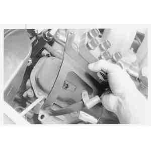
| Fig. 7: To remove the valve cover, first disconnect
the crankcase breather vent tube
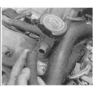
|
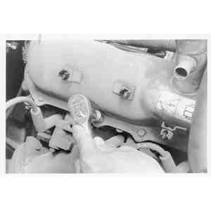
| Fig. 8: Label and unplug any electrical connections
. . .
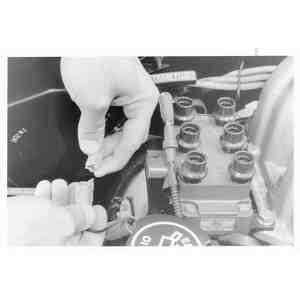
|
| Fig. 9: . . . as well as vacuum fittings which
will inhibit valve cover removal
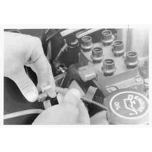
|
| Fig. 10: Remove the coil pack mounting bracket
attaching bolts . . .
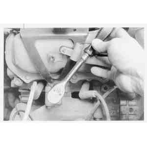
|
| Fig. 11: . . . then remove the coil pack and
bracket from the engine
|
- Remove the ignition coil pack.
- Move the any wiring harnesses out of the way.
- Disconnect the oil filler neck vacuum hose.
- Remove the right wiring harness by pulling up on the clip.
- If removing the left valve cover, perform the following steps:
- Remove the upper intake manifold.
- If equipped, disengage the A/C compressor clutch connector.
- If equipped, remove the A/C compressor mounting bolts and position the
compressor off to the side.
- Disconnect the power brake vacuum hose.
- Disconnect and tag the hoses connected to the vacuum tee.
- Remove the PCV valve.
- Remove the left wiring harness by pulling up on the clip.
- Remove the fuel hose clip bolt and position the hoses to gain access
to the upper cover bolts.
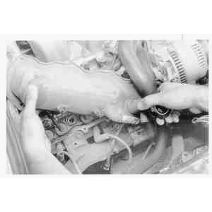
| Fig. 12: Remove the valve cover hold-down bolts
. . .
|
| Fig. 13: . . . then remove the cover from the
engine. A slight tap with a soft-faced hammer helps to break the
seal
|
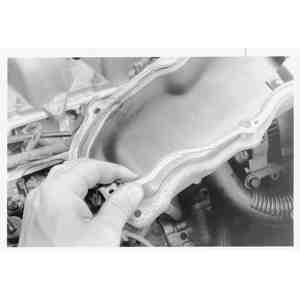
| Fig. 14: Remove the old valve cover gasket and
discard
|
- Remove the valve cover mounting bolts and reinforcement plates.
- Remove the valve cover(s). It will probably be necessary to tap the cover
loose with a plastic or rubber mallet.
- Remove the valve cover gaskets.
To install:
- Clean all gasket material from the cover and head.
| Fig. 15: Rocker arm cover installation on 4.0L engines
|
- Before installing the new gasket(s), apply sealant to the seam between the
lower intake manifold and cylinder head and a 0.125 inch (8mm) ball to each
bolt hole on the exhaust manifold side of the cylinder head cover.
- Install the new gasket(s).
- Install the valve cover onto the cylinder head in correct position, then
install the reinforcement plates and mounting bolts. Tighten the mounting
bolts to 5–6 ft. lbs. (6–8 Nm).
- If installing the left valve cover, perform the following steps:
- Position the fuel hoses correectly and install the fuel hose clip bolt.
- Install the left wiring harness and push down on the clip.
- Install the PCV valve.
- Connect the hoses to the vacuum tee.
- Connect the power brake vacuum hose.
- Install the A/C compressor in position onto the mounting bracket, if
equipped. Tighten the mounting bolts to 18–23 ft. lbs. (24–30
Nm).
- Plug in the A/C compressor clutch connector, if equipped.
- Install the upper intake manifold.
- If installing the right valve cover, perform the following steps:
- Install the right wiring harness and push down on the clip.
- Connect the oil filler neck vacuum hose.
- Place the wiring harnesses back in position on top of the valve cover.
- Install the ignition coil pack.
- Install the alternator.
- Connect the spark plug wires.
- Install the A/C pipe bolt to the upper intake manifold, if equipped.
- Install the air inlet duct hose.
- Install the accelerator cable shield.
- Connect the negative battery cable.
NOTE: Failure to install new valve cover gaskets and valve
cover reinforcement pieces will result in oil leaks.
- Disconnect the negative battery cable.
- If removing the right valve cover, perform the following steps:
- Remove the air cleaner outlet tube.
- Drain the cooling system.
- Remove the upper radiator hose.
- Disengage the engine control sensor wiring from the Mass Air Flow (MAF)
sensor and alternator.
- Disconnect the heater water hose.
- Disconnect the cruise control actuator cable.
- Disconnect the hose from the vacuum reservoir.
- Disconnect and tag the spark plug wires.
- If removing the left valve cover, perform the following steps:
- Remove the upper intake manifold.
- Disconnect the vacuum lines from the EGR valve.
- Loosen the mounting bolts and remove the EGR valve.
- Remove the nut and stud bolt.
- Remove the valve cover mounting bolts and stud bolt.
- Remove the valve cover(s). It will probably be necessary to tap the cover
loose with a plastic or rubber mallet.
- Remove the valve cover gaskets.
To install:
| Fig. 16: Apply a bead of silicone sealant in two
places before installing the valve cover

|
| Fig. 17: Valve cover mounting fastener tightening
sequence

|
- Clean all gasket material from the cover and head.
- Before installing the new gasket(s), apply a 0.24 inch (6mm) bead of silicone
sealant to the seam between the lower intake manifold and cylinder head.
- Install the new gasket(s).
- Install the valve cover onto the cylinder head in correct position, then
install the mounting bolts. Tighten the mounting bolts in correct sequence
to 54–70 inch lbs. (6–8 Nm).
- If installing the left valve cover, perform the following steps:
- Install the nut and stud bolt, then install the EGR valve.
- Connect the vacuum lines to the EGR valve.
- Install the upper intake manifold.
- If installing the right valve cover, perform the following steps:
- Connect the spark plug wires.
- Connect the hose to the vacuum reservoir.
- Connect the cruise control actuator cable.
- Connect the heater water hose.
- Engage the engine control sensor wiring to the MAF sensor and alternator.
- Connect the upper radiator hose.
- Install the air cleaner outlet tube.
- Refill the cooling system.
- Connect the negative battery cable.