NOTE: The fuel vapor canister is also referred to as evaporative
emissions canister or charcoal canister.
Generally, the only testing done to the vapor canister is a visual inspection.
Look the canister over and replace it with a new one if there is any evidence
of cracks or other damage.
NOTE: Do not try to check the fuel saturation of the canister
by weighing it or by the intensity of the fuel odor from the canister. These
methods are unreliable and inhaling gasoline fumes can be toxic.
NOTE: The cut valve was previously referred to as the check
& cut valve on 1994–95 MPV models.
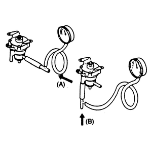
| Fig. 1: Testing the cut valve using a vacuum gauge
|
- Remove the cut valve from the vehicle.
- Hold the valve in the horizontal position, otherwise the weight of the valve
will cause it to move out of position and close the passage.
- Connect a vacuum gauge in line to the passage which normally connects to
the fuel tank — port A.
- Blow air into port A and verify that the valve opens at
a pressure of 0.79-0.99 psi (5.40-6.86kpa).
- Remove the vacuum gauge and connect it to the passage to atmosphere — port B.
- Blow air into port B and verify that the valve opens at
a pressure of 0.15-0.71 psi (0.99-4.91kpa).
- If not as specified, replace the valve.
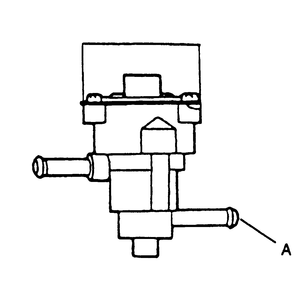
| Fig. 2: Location of cut valve vacuum port A
|
- Remove the cut valve from the vehicle.
- While holding the valve in the horizontal position, blow air into port A and
verify that their is air flow through the valve.
- Next, hold the valve in the tilted position and blow air through port A again.
- Verify that air does not flow through the valve.
- If not as specified, replace the cut valve.
NOTE: The check valve is also referred to as the two-way check
valve.
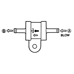
| Fig. 3: Two-way check valve testing
|
- Remove the check valve and blow air through port A and
check that the air flows.
- Blow air through the opposite side port (port B) and check that
the air does not flow through the valve.
- Replace the valve as required.
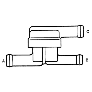
| Fig. 4: Vacuum port identification for testing the check
valve
|
- Remove the check valve and blow air through port B and
check that the air flows smoothly through port C.
- Blow air into port C and check that the air flows smoothly
through port A.
- Replace the valve as required.
- Remove the canister purge control solenoid.
- Using an external voltage source, apply 9–14 DC volts to the purge
solenoid electrical terminals. Then, use a hand-held vacuum pump and apply
16 in. Hg (53 kPa) vacuum to the manifold side nipple of the solenoid.
- If the solenoid opens and allows air to freely pass through it, the
solenoid is working properly.
- If the solenoid does not allow air to pass freely while energized, replace
the solenoid with a new one.
- Remove the canister purge control solenoid.
- Measure the resistance between the two solenoid terminals.
- If the resistance is between 30–90 ohms, proceed to the Step 3.
- If the resistance is not between 30–90 ohms, replace the solenoid.
- Attach a hand-held vacuum pump to the intake manifold vacuum side of the
purge solenoid, then apply 16 in. Hg (53 kPa) of vacuum to the solenoid.
- If the solenoid will not hold vacuum for at least 20 seconds replace
it with a new one.
- If the solenoid holds vacuum, proceed to Step 4. Keep the vacuum applied
to the solenoid.
- Using an external voltage source, apply 9–14 DC volts to the solenoid
electrical terminals.
- If the solenoid opens and the vacuum drops, the solenoid is working
properly.
- If the solenoid does not open and the vacuum remains, replace the solenoid
with a new one.
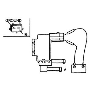
| Fig. 5: Testing the canister purge solenoid valve
|
- Start the vehicle and warm the engine.
- Disconnect the vacuum hose (usually white) closest to the wire connector
from the solenoid valve.
- Verify there is no vacuum at the solenoid valve at idle speed.
- If there is vacuum at the solenoid valve, turn the engine OFF.
- Disconnect the other vacuum hose and apply air pressure. Verify that no
air flows through the valve.
- Next, supply 12 volts to the terminals of the solenoid. Apply air pressure
(port A) and verify that air does flow through the valve.
- If not as specified, replace the solenoid valve.

