Fuel vapors trapped in the sealed fuel tank are vented through the fuel vapor valve assembly in the top of the tank, or vent cut valve at the fuel tank filler tube. The vapors leave the valve assembly through a single vapor line and continue to the carbon canister for storage until they are purged to the engine for burning.
Purging the carbon canister removes the fuel vapor stored in the carbon canister. The fuel vapor is purged via a purge control solenoid or vacuum controlled purge valve. Purging occurs when the engine is at normal operating temperature and off idle.
The evaporative emission control system consists of the following components: fuel vapor (charcoal) canister, fuel vapor valve (Navajo and 1994–97 B Series Pick-up), fuel separator (MPV), cut valve (MPV), check valve (MPV), fuel vapor canister purge solenoid, pressure/vacuum relief fuel tank filler cap, as well as, the fuel tank and fuel tank filler pipe, vapor tube and fuel vapor hoses.
| Fig. 1: Evaporative canister and hose routing on the
2.3L engine
|
| Fig. 2: Evaporative canister and hose routing on the
3.0L engine for 1994–97 B Series Pick-up
|
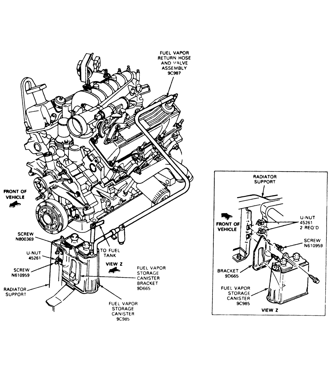
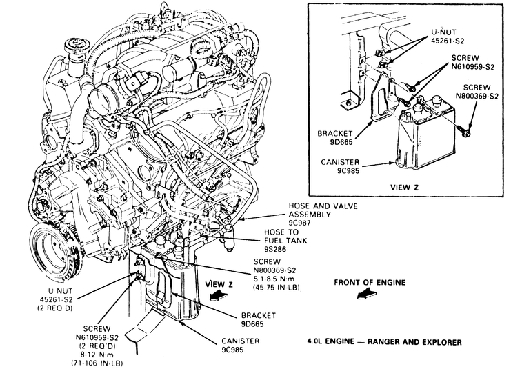
| Fig. 3: Evaporative canister and hose routing on the
4.0L engine for 1994–97 B Series Pick-up and Navajo models
|
| Fig. 4: Evaporative canister and hose routing for all
1998 B Series Pick-up engines — note location of the canister
purge control solenoid
|
| Fig. 5: Evaporative canister location — 1994–95
MPV models
|
| Fig. 6: Evaporative canister assembly — 1996–98
MPV models
|
NOTE: The fuel vapor canister is also referred to as evaporative emissions canister or charcoal canister.
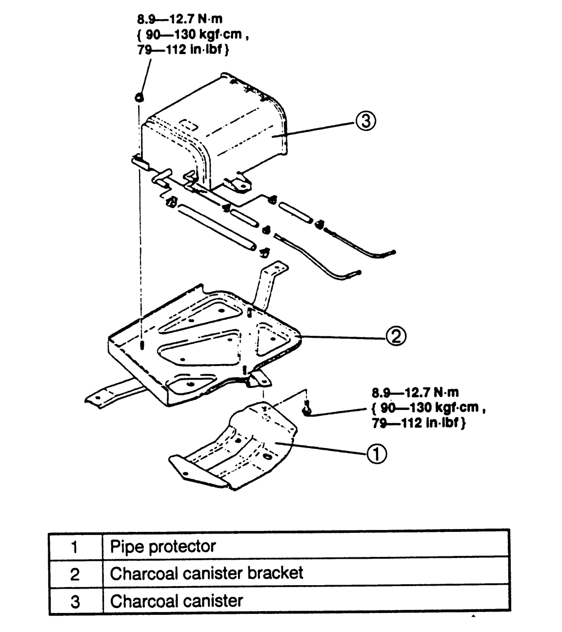
The fuel vapors from the fuel tank are stored in the fuel vapor canister until the vehicle is operated, at which time, the vapors will purge from the canister into the engine for consumption. The fuel vapor canister contains activated carbon, which absorbs the fuel vapor. The fuel vapor canister can be found in the following locations:
NOTE: This component is also known as the evaporative emission valve on 1995–98 models.
Fuel vapor in the fuel tank is vented to the carbon canister through the vapor valve assembly. The valve is mounted in a rubber grommet at a central location in the upper surface of the fuel tank. A vapor space between the fuel level and the tank upper surface is combined with a small orifice and float shut-off valve in the vapor valve assembly to prevent liquid fuel from passing to the carbon canister. The vapor space also allows for thermal expansion of the fuel.
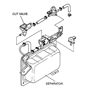
| Fig. 7: Fuel separator and cut valve assembly
|
The fuel separator is the component that prevents fuel from flowing into the fuel vapor canister. The fuel separator is located on the right side rear wheelhouse behind the interior trim panel. The fuel separator is not serviceable and should be checked periodically for damage or leaking. Replace the separator if damage or leaking is evident.
NOTE: The cut valve was previously referred to as the check & cut valve on 1994–95 MPV models.
The cut valve is mounted on top of the fuel separator, which is located on the right side rear wheelhouse behind the interior trim panel. The cut valve when necessary, releases excessive pressure or vacuum in the fuel tank to the atmosphere.
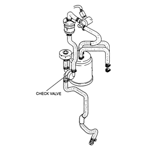
| Fig. 8: Check valve location on 1996–98 MPV models
|
NOTE: The check valve is also referred to as the two-way check valve.
On 1994–95 MPV models, the (two-way) check valve is mounted on top of the fuel separator, which is located on the right side rear wheelhouse behind the interior trim panel. On 1996–98 MPV models, the check valve is located on the right side of the engine compartment near the firewall. The check valve is used to control pressure in the fuel tank.
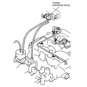
| Fig. 9: Location of the canister purge solenoid on 1996–98
MPV models
|
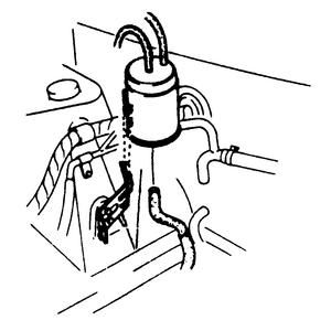
The canister purge control solenoid is inline with the carbon canister and controls the flow of fuel vapors out of the canister. It is normally closed. When the engine is shut OFF, the vapors from the fuel tank flow into the canister. After the engine is started, the solenoid is engaged and opens, purging the vapors into the engine. With the solenoid open, vapors from the fuel tank are routed directly into the engine. The canister purge control solenoid can be found in the following locations:
The fuel cap contains an integral pressure and vacuum relief valve. The vacuum valve acts to allow air into the fuel tank to replace the fuel as it is used, while preventing vapors from escaping the tank through the atmosphere. The vacuum relief valve opens after a vacuum of approximately–0.25 psi (1.7 kPa). The pressure valve acts as a backup pressure relief valve in the event the normal venting system is overcome by excessive generation of internal pressure or restriction of the normal venting system. The pressure relief is approximately 2 psi (14 kPa). Fill cap damage or contamination that stops the pressure vacuum valve from working may result in deformation of the fuel tank.