Previous Next

TESTING

B Series Pick-up and Navajo Models
  1. Disconnect the negative battery cable.
  2. Disengage the wiring harness connector from the TP sensor.
  3. Using a Digital Volt-Ohmmeter (DVOM) set on ohmmeter function, probe the terminals, which correspond to the Brown/White and the Gray/White connector wires, on the TP sensor. Do not measure the wiring harness connector terminals, rather the terminals on the sensor itself.
  4. Slowly rotate the throttle shaft and monitor the ohmmeter for a continuous, steady change in resistance. Any sudden jumps, or irregularities (such as jumping back and forth) in resistance indicates a malfunctioning sensor.
  5. Reconnect the negative battery cable.
  6. Turn the DVOM to the voltmeter setting.

    WARNING
    Ensuring the DVOM is on the voltmeter function is vitally important, because if you measure circuit resistance (ohmmeter function) with the battery cable connected, your DVOM will be destroyed.

  7. Detach the wiring harness connector from the PCM (located behind the lower right-hand kick panel in the passengers' compartment), then install a break-out box between the wiring harness connector and the PCM connector.
  8. Turn the ignition switch ON and using the DVOM on voltmeter function, measure the voltage between terminals 89 and 90 of the breakout box. The specification is 0.9 volts.
  9. If the voltage is outside the standard value or if it does not change smoothly, inspect the circuit wiring and/or replace the TP sensor.

    Fig. 1: TP sensor wire harness connections

MPV Models

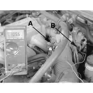
Fig. 2: Checking the resistance of the ignition switch within the TPS housing using a feeler gauge (A) and an ohmmeter on terminals C and D (B)

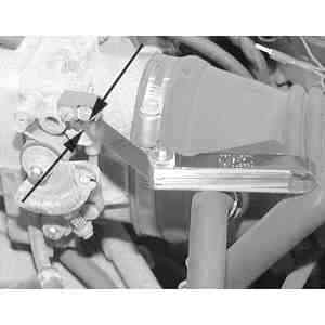
Fig. 3: Place a feeler gauge between the throttle lever and throttle lever stop

  1. Verify that the throttle valve is at the closed throttle position.
  2. Disengage the wiring harness connector from the TP sensor.
  3. Using a Digital Volt-Ohmmeter (DVOM) set on ohmmeter function, probe terminals C and D on the TP sensor.
  4. Insert a 0.020 inch (0.50mm) feeler gauge between the throttle adjusting screw and the throttle lever. Verify that there is no continuity.
  5. If there is no continuity, adjust the TPS as follows:
    1. Loosen the TPS mounting screws.
    2. Insert a feeler gauge between the throttle adjusting screw and the throttle lever.
    3. There should be continuity when inserting a 0.006 inch (0.15mm) feeler gauge and there should be NO continuity when inserting a 0.020 inch (0.50mm) feeler gauge.
    4. Tighten the mounting screws.
  6. Replace the TPS if not as specified.

Previous Next