- Remove the upper intake manifold. Be sure to depressurize the fuel system
before disconnecting any fuel lines.
- Disconnect the fuel supply and return line retaining clips.
- Detach the vacuum line from the fuel pressure regulator.
- Disconnect the fuel chassis inlet and outlet fuel hoses from the fuel supply
manifold.
| Fig. 1: Exploded view of the 2.3L engine fuel supply
rail and injectors — 2.5L engine similar
|
| Fig. 2: Exploded view of the 3.0L engine fuel supply
rail and injectors
|
| Fig. 3: Exploded view of the 4.0L engine fuel supply
rail and injectors
|
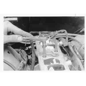
| Fig. 4: For fuel supply manifold removal, unbolt
the upper intake, then disconnect the injector wire harness plugs
|
- Label and disconnect the fuel injector wire harness plugs.
- On the 2.3L engine, remove the two fuel supply manifold retaining bolts.
- On the 4.0L engine, remove the six upper intake manifold attaching studs.
| Fig. 5: On the 4.0L engine, remove the 6 manifold
mounting studs which retain the supply manifold
|
- On all other engines, remove the four fuel supply manifold retaining bolts.
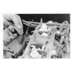
- Carefully disengage the fuel rail assembly from the fuel injectors by lifting
and gently rocking the rail.
| Fig. 6: Some models use small retaining clips to
secure the injectors in the supply manifold
|
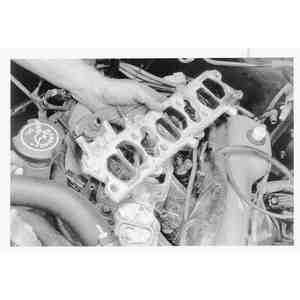
| Fig. 7: Lift upwards with a rocking motion to disengage
the injectors, then remove the supply manifold
|
| Fig. 8: On the 4.0L engine, remove the old fuel supply
manifold gasket and clean the mating surfaces

|
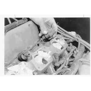
- Remove the fuel injectors from the intake manifold by lifting while gently
rocking them from side to side
| Fig. 9: Remove the injectors from the engine by gently
rocking it while pulling upwards
|
- Place all removed components on a clean surface to prevent contamination
by dirt or grease.
NOTE: Never use silicone grease; it will clog the injector.
All injectors and the fuel rail must be handled with extreme care to prevent
damage to sealing areas and sensitive fuel metering orifices.
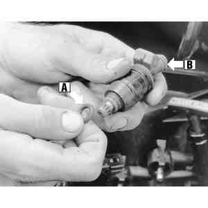
| Fig. 10: The injector has O-rings at the nozzle (A)
and at the fuel supply manifold (B). Replace any damaged seals
|
- Examine the injector O-rings for deterioration damage, replacing them as
needed.
- Make sure the injector caps are clean and free from contamination or damage.
To install:
- Lubricate all O-rings with clean engine oil, then install the injectors
into the fuel rail using a light twisting/pushing motion.
- On the 4.0L engine, position a new fuel rail gasket to the lower intake
manifold.
- Carefully install the fuel rail assembly and injectors into the lower intake
manifold. Make certain to correctly position the insulators. Push down on
the fuel rail to make sure the O-rings are seated.
- Hold the fuel rail assembly in place and install the retaining bolts finger
tight. Then tighten the bolts to specifications.
- Connect the fuel supply and return lines.
- Attach the vacuum hose to the fuel pressure regulator.
- Connect the fuel injector wiring harness at the injectors.
- Connect the vacuum line to the fuel pressure regulator, if removed.
- Install the air intake and throttle body assembly.
- Run the engine and check for fuel leaks.
CAUTION
Fuel injection systems remain under pressure after the engine has been turned
OFF. Properly relieve fuel pressure before disconnecting any fuel lines. Failure
to do so may result in fire or personal injury.
CAUTION
Do not allow fuel spray or fuel vapors to come in contact with a spark or open
flame. Keep a dry chemical fire extinguisher nearby. Never store fuel in an
open container due to risk of fire or explosion.
- Relieve the fuel system pressure.
- Disconnect the negative battery cable.
- Remove the upper intake manifold (dynamic chamber) as follows:
- Remove the manifold brackets.
- Disconnect and label the PCV hose, intake temperature sensor and ground
wire.
- Remove the fuel injector harness bracket, and then remove the upper
intake manifold.
| Fig. 11: Dynamic chamber and related components — 2.6L
engine
|
- Label and disconnect the vacuum and fuel hoses from the fuel rail.
- Remove the fuel rail with the pressure regulator attached.
- Disconnect the injector harness from injectors.
- Invert fuel injector rail assembly.
- Remove lock rings securing injectors to fuel rail receiver cups. Pull injectors
upward from receiver cups.
- If injectors are to be reused, place a protective cap on injector nozzle
to prevent dirt or other damage.
To install:
- Lubricate the new O-ring of each injectors with a clean drop of engine oil
prior to installation.
- Assemble each injector into the fuel rail receiver cups. Be careful not
to damage the O-rings.
- Install lock ring between receiver cup ridge and injector slot.
- Install the fuel rail. Connect the vacuum and fuel hoses.
- Install the upper intake manifold (dynamic chamber). Tighten the mounting
bolts for the manifold and brackets to 14–18 ft. lbs. (19–25 Nm).
- Connect the negative battery cable.
- Start the engine and examine for leaks.
CAUTION
Fuel injection systems remain under pressure after the engine has been turned
OFF. Properly relieve fuel pressure before disconnecting any fuel lines. Failure
to do so may result in fire or personal injury.
CAUTION
Fuel injection systems remain under pressure after the engine has been turned
OFF. Properly relieve fuel pressure before disconnecting any fuel lines. Failure
to do so may result in fire or personal injury.
- Disconnect the negative battery cable.
- Drain the coolant system.
- Remove the air and water hoses.
- Remove the air cleaner assembly.
- Disconnect the accelerator cable.
- Disengage the throttle position sensor connector.
| Fig. 12: Throttle body and related components — 3.0L
engine
|
- Remove the throttle body and gasket.
- Remove the Bypass Air Control (BAC) valve and intake air pipe.
- Remove the extension manifolds.
| Fig. 13: Dynamic chamber and related components — 3.0L
engines
|
- Remove the dynamic chamber.
- Disconnect the fuel lines and electrical connectors.
- Remove the fuel rail.
- Disconnect the injector harness from injectors.
- Invert the fuel injector rail assembly.
- Remove the lock rings securing the injectors to the fuel rail receiver cups.
Pull the injectors upward from the receiver cups.
- If the injectors are to be reused, place a protective cap on the injector
nozzle to prevent dirt or other damage.
To install:
- Lubricate the new O-ring of each injectors with a clean drop of engine oil
prior to installation.
- Assemble each injector into the fuel rail receiver cups. Be careful not
to damage the O-rings.
- Install a lock ring between the receiver cup ridge and injector slot.
- Install the fuel rail.
- Connect the fuel lines and electrical connectors.
- Install the dynamic chamber.
- Install the extension manifolds.
- Install the intake air pipe, with a new gasket, and BAC valve.
- Install the throttle body with a new gasket.
- Engage the throttle position sensor connector.
- Connect and adjust the accelerator cable.
- Install the air cleaner assembly.
- Install the air and water hoses.
- Fill and bleed the coolant system.
- Connect the negative battery cable.