Previous Next

REMOVAL & INSTALLATION

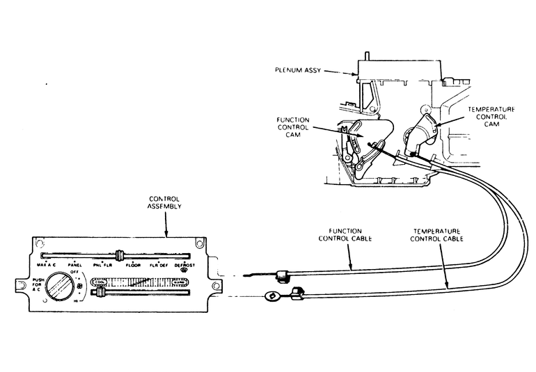
Fig. 1: Control cable connections at the head and the air plenum

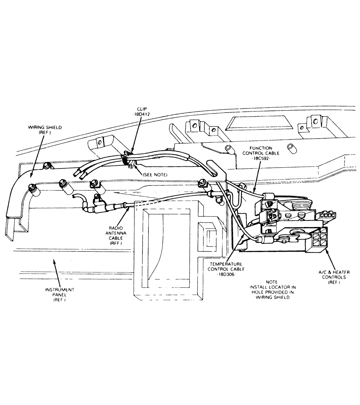
Fig. 2: Control cable routing diagram

Navajo and B Series Pick-up Models
  1. Disconnect the negative battery cable.
  2. Remove the control assembly from the instrument panel.
  3. Disengage the glove compartment door by squeezing the sides together and allowing the door to hang free.
  4. Working through the glove compartment and/or control opening, remove the temperature and function cable jackets from their clips on top of the plenum by compressing the clip tangs and pulling the cables upward.
  5. Reach through the glove compartment opening and disconnect the function and temperature cables from their separate cams. The cable ends are secured to the cams under a retention finger.
  6. The cables are routed inside the instrument panel with 2 routing aids. Remove the cables from these devices. Reaching through the control opening, pull the cables upward out of the wiring shield cut-out. Reaching through the glove box opening, pull the cables out of the plastic clip up inside the instrument panel.
  7. Pull the cables from the instrument panel through the control assembly opening.

    To install:

  8. Working through the glove compartment opening and the control opening in the instrument panel, feed the end of the cables to the cam area. Feed the cables in from the glove compartment opening, making sure the coiled end of the white function cable and the round hole diecast end of the temperature cable go in first.
  9. Attach the coiled end of the function cable to the function cam, making sure the cable is routed under the cable hold-down feature on the cam assembly. The pigtail coil may be facing either up or down.
  10. Attach the diecast end of the temperature cable to the temperature cam making sure the cable is routed under the cable hold-down feature on the cam assembly.
  11. Route the control end of the cable through the instrument panel until the ends stick out of the control opening. It is not necessary to insert the cable into any routing devices previously used. The routing aids are only necessary when the entire instrument panel is removed and reinstalled.
  12. Attach the function and temperature cables to the control. Install the control assembly in the instrument panel.
  13. Adjust the cables in their clips on top of the plenum.

    NOTE: Make sure the radio antenna cable does not become disengaged from its mounting and fall into the plenum cam area where it could cause an increase in control assembly operating effort or a faulty selection of system functions.

  14. Connect the negative battery cable and make a final check of the system for proper control cable operation.
MPV Models
  1. Remove the control head unit.
  2. Disconnect the air intake wire from the front blower unit.
  3. Disconnect the air mix and airflow mode wires from the front heater unit.
  4. Disconnect the control wires from the control unit.

    To install:

  5. Connect the control wires to the control unit.
  6. Connect the air mix and airflow mode wires to the front heater unit, then adjust.
  7. Connect the air intake wire to the front blower unit and adjust.
  8. Install the control head unit into the dashboard.

Previous Next