Previous Next

REMOVAL & INSTALLATION

Navajo and B Series Pick-up Models

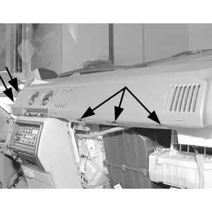
Fig. 1: Exploded view of a cable equipped control head

Fig. 2: Front and rear view of a cableless control head

  1. Disconnect the negative battery cable.
  2. On 1994 models, open the ash tray and remove the 2 screws that hold the ash tray drawer slide to the instrument panel. Remove the ash tray and drawer slide bracket from the instrument panel.
  3. On 1995–98 models, remove the radio.
  4. Gently pull the finish panel away from the instrument panel and the cluster. The finish panel pops straight back for approximately 1 inch (25.4mm), then up to remove. Be careful not to trap the finish panel around the steering column.

    NOTE: If equipped with the electronic 4x4 shift-on-the-fly module, disconnect the wire from the rear of the 4x4 transfer switch before trying to remove the finish panel from the instrument panel.

  5. Remove the 4 screws attaching the control assembly to the instrument panel.
  6. Pull the control through the instrument panel opening far enough to allow removal of the electrical connections from the blower switch and control assembly illumination lamp. Using a suitable tool, remove the vacuum harness from the vacuum switch on the side of the control.
  7. If equipped with cables, perform the following:
    1. At the rear of the control, using a suitable tool, release the temperature and function cable snap-in flags from the white control bracket.
    2. On the bottom side of the control, remove the temperature cable from the control by rotating the cable until the T-pin releases the cable. The temperature cable is black with a blue snap-in flag.
    3. Pull enough cable through the instrument panel opening until the function cable can be held vertical to the control, then remove the control cable from the function lever. The function cable is white with a black snap-in flag.
  8. Remove the control assembly from the instrument panel.

    To install:

  9. If equipped with control cables, perform the following:
    1. Pull the control cables through the control assembly opening in the instrument panel for a distance of approximately 8 in. (203mm).
    2. Hold the control assembly up to the instrument panel with its face directed toward the floor of the vehicle. This will locate the face of the control in a position that is 90 degrees out of its installed position.
    3. Carefully bend and attach the function cable that has a white color code and a black snap-in terminal to the white plastic lever on the control assembly. Rotate the control assembly back to its normal position for installation, then snap the black cable flag into the control assembly bracket.
    4. On the opposite side of the control assembly, attach the black temperature control cable with the blue plastic snap-in flag to the blue plastic lever on the control. Make sure the end of the cable is seated securely with the T-top pin on the control. Rotate the cable to its operating position and snap the blue cable flag into the control assembly bracket.
  10. Connect the wiring harness to the blower switch and the illumination lamp to its receptacle on the control assembly. Connect the terminal on the vacuum hose to the vacuum switch on the control assembly.
  11. Position the control assembly into the instrument panel opening and install the 4 mounting screws.
  12. If equipped, reconnect the 4x4 electric shift harness on the rear of the cluster finish panel.
  13. Install the cluster finish panel with integral push-pins. Make sure that all pins are fully seated around the rim of the panel.
  14. On 1994 models, reinsert the ash tray slide bracket and reconnect the illumination connection circuit. Reinstall the 2 screws that retain the ash tray retainer bracket and the finish panel. Replace the ash tray and reconnect the cigarette lighter.
  15. On 1995–98 models, reinstall the radio.
  16. Connect the negative battery cable and check the heater system for proper control assembly operation.
1994–95 MPV Models
WIRE TYPE

Fig. 3: Remove the three mounting screws on the right side of the lower center panel, then remove the three mounting screws on the left side

Fig. 4: Remove the lower center panel from the vehicle

  1. Disconnect the negative battery cable.
  2. Remove the left and right side lower dash panels and the lower center panel. Remove the steering column cover, if required.

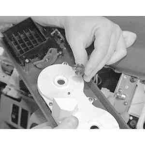
    Fig. 5: Remove the temperature control and fan speed knobs by pulling straight off

    Fig. 6: Remove the switch panel mounting screws to access the temperature control assembly

    Fig. 7: Turn the switch panel light socket counterclockwise and pull out of the switch panel housing

  3. Remove the instrument cluster hood assembly. Remove the switch panel knobs, attaching nuts and washers. Remove the switch panel.
  4. Remove the attaching screws and remove the temperature control assembly. Remove the airflow mode control unit attaching screws. Remove the control assembly and disconnect the wire connectors.

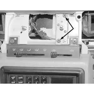
    Fig. 8: Remove the two temperature control assembly mounting screws

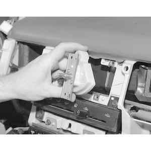
    Fig. 9: Remove the temperature control assembly after removing the mounting screws

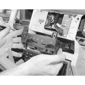
    Fig. 10: After disconnecting the control wires and removing the 4 mounting screws, pull out the control panel head

  5. Install in reverse order.
  6. Adjust the control wires.
LOGIC TYPE
  1. Remove the instrument cluster hood.
  2. Remove the left and right side lower dash panels and the lower center panel.
  3. Remove the control unit mounting screws and pull the unit out enough to disengage the wiring harness connectors.
  4. Installation is the reverse of the removal procedure.
1996–98 MPV Models
  1. Disconnect the negative battery cable.
  2. Remove the side panel on the left side of the dashboard.
  3. Remove the left side lower panel.

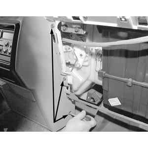
    Fig. 11: Disengage the retaining clips and remove the left side panel from the dashboard

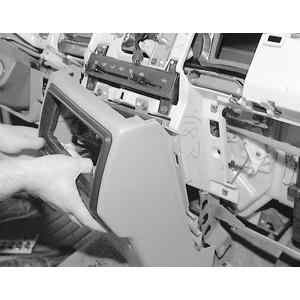
    Fig. 12: Remove the mounting screws and disengage the retaining clips, then remove the left side lower cover

    Fig. 13: Release the left and right pins, then remove the glove compartment

    Fig. 14: After removing the right side panel, remove the glove compartment cover

  4. Remove the glove compartment.
  5. Remove the side panel on the right side of the dashboard, then remove the glove compartment cover.
  6. Remove the center lower panel.
  7. Remove the center upper panel.
  8. Disconnect the air intake wire from the front blower unit.
  9. Disconnect the air mix and airflow mode wires from the front heater unit.
  10. Disconnect the control unit mounting screws.
  11. Pull out the control unit enough to disengage the electrical connectors and remove from the vehicle.

    Fig. 15: Remove the mounting screws, disengage the retaining clips and remove the center lower panel

    Fig. 16: Remove the center upper panel by removing the two mounting screws and disengaging the retaining clips

    Fig. 17: Exploded view of the control unit assembly

    To install:

  12. Install the control unit into the dashboard and attach the electrical connectors.
  13. Install and tighten the mounting screws.
  14. Connect the air mix and airflow mode wires to the front heater unit, then adjust.
  15. Connect the air intake wire to the front blower unit and adjust.
  16. Install the center upper panel.
  17. Install the center lower panel.
  18. Install the glove compartment cover.
  19. Install the glove compartment.
  20. Install the lower panel.
  21. Install the side panel.
  22. Connect the negative battery cable. Check the operation of the control unit.

Previous Next