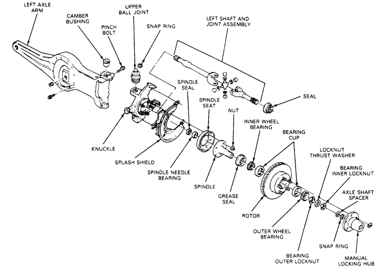
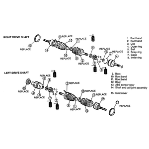
| Fig. 1: Exploded view of the left-hand axle shaft assembly
and related components
|
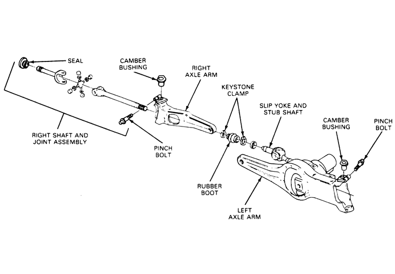
| Fig. 2: Exploded view of the right-hand axle shaft assembly
and related components
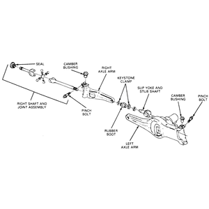
|
- Loosen the front wheel lug nuts.
- Raise and support the vehicle safely. Remove the wheel and tire assembly.
- Remove the disc brake calipers and support the caliper on the vehicle's
frame rail.
- Remove the hub locks and lock nuts.
- Remove the hub and rotor.
- Remove the nuts retaining the spindle to the steering knuckle. Tap the spindle
with a plastic or rawhide hammer to jar the spindle from the knuckle.
- Remove the front disc brake rotor shield.
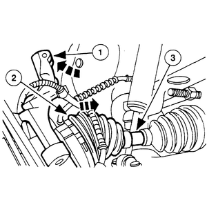
NOTE: The left-hand axle shaft is engaged inside of the
front carrier assembly. Depending on how the truck is sitting (especially
if it is not level), some fluid may leak out of the front carrier assembly.
A small drip pan should can be placed underneath the front carrier as a
precautionary measure.
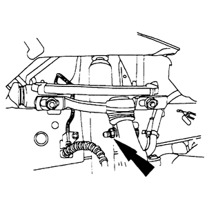
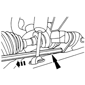
| Fig. 3: Pull the axle shaft assemble out through
the hole in the steering knuckle
|
- Remove the left-hand side axle shaft by pulling the assembly out of the
carrier and through the hole in the steering knuckle (spindle mount).
- Remove the right-hand axle shaft by performing the following:
- Remove and discard the right front axle joint boot clamp from the outer
axle assembly.
- Pull the right-hand axle shaft out of the axle joint boot and stub shaft
and through the hole in the steering knuckle (spindle mount).
- Inspect the seals on the outer axle shaft ends, and replace them if necessary.
Replace the seals as follows:
- Remove the old seal from the axle shaft by driving them off with a hammer.
- Thoroughly clean the axle seal area of the shaft.
- Place the shaft in a press and install the new seal using the Spindle/Axle
Seal Installer Tool T83T-3132-A, or equivalent.
To install:
- Install the right-hand axle shaft as follows:
- Ensure that the rubber boot is properly installed on the carrier stub
shaft. Slide a new outer axle shaft boot clamp onto the rubber boot.
NOTE: The model 35 front axle does not use blind, or
master, splines. Therefore, special attention should be made to ensure
that the yoke ears are in line (in phase) during assembly.
- Slide the right axle shaft assemble through the hole in the steering
knuckle, into the rubber boot and engage the splines of the stub shaft.
Ensure the splines are fully engaged.
- Position the rubber boot and clamp onto the outer axle shaft and crimp
the clamp securely on the rubber boot using Keystone Clamp Pliers T63P-9171-A.
- Install the left-hand axle shaft by sliding it through the hole in the steering
knuckle and engaging it into the carrier. Ensure that the shaft is fully seated
into the carrier and engage to the splines inside.
- Install the front disc brake rotor shield, spindle and retaining nuts.
- Install the front brake rotors, bearings, locknuts and hubs.
- Install the brake caliper and wheel assembly.
- Lower the vehicle. Tighten the lug nuts to specification.
WARNING
Do not perform this procedure unless a new wheel hub nut and washer assembly
and a new axle shaft circlip are available. Once removed, these parts must never
be reused during assembly.
- Loosen the front wheel lug nuts.
- Raise and safely support the vehicle.
- Remove the wheels.
- Remove and discard the center wheel hub nut and washer.
WARNING
Never reuse the wheel hub nut and washer. This nut is a torque prevailing
design and cannot be reused.
- Remove the disc brake caliper and position it aside.
NOTE: The hub shaft is a slip fit into the wheel hub and
bearing; a press is not normally required.
- Ensure that the wheel hub shaft can be pushed inwards. If not, assemble
a press to the front wheel studs and press the wheel hub shaft inwards slightly
to break it loose.
- Place a jack under the lower control arm to support it.
- Remove the upper ball joint-to-steering knuckle retaining bolt and separate
the joint from the knuckle.
WARNING
Support the steering knuckle and do not allow it to drop or swing downwards.
This can overstress the CV-boot and joint, causing damage.
| Fig. 4: Remove the wheel hub nut (arrow) and discard
it. NEVER reuse the wheel hub nut
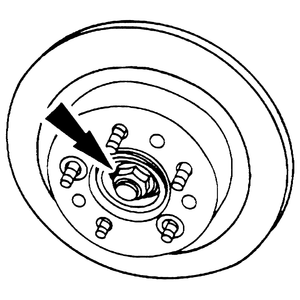
|
| Fig. 5: Remove the upper ball joint-to-steering knuckle
retaining bolt
|
| Fig. 6: Rotate the knuckle (1) downward and pull
the CV-joint (2) out of the wheel hub by compressing the axle shaft
(3) inward
|
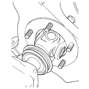
| Fig. 7: Using a CV-joint puller (arrow) to remove
the inboard joint from the axle housing
|
| Fig. 8: Pull the entire halfshaft from the vehicle
|
- Remove the outboard CV-joint from the wheel hub by slightly rotating the
steering knuckle down, taking care not to overstress the joint or boot, and
pulling the CV-joint out from the hub.
- Use a CV-joint puller and impact slide hammer to pull the inboard CV-joint
from the axle housing. You can also use a prytool to carefully pry the CV-joint
outward to disengage the internal circlip. Take care to not damage the axle
housing seal.
- Remove the halfshaft from the vehicle. Remove the circlip from the inboard
CV-joint end and discard it.
To install:
- Install a new circlip to the inboard CV-joint end.
- Position the halfshaft into the vehicle. Slide the inboard CV-joint end
into the axle housing until it is fully seated. Ensure that the circlip is
engaged in the housing by attempting to pull the joint outwards.
- Install the outboard CV-joint end into the wheel hub.
- Position the upper ball joint to the steering knuckle and install the retaining
bolt.
- Install the disc brake caliper back onto the rotor.
- Install a new wheel hub nut and washer and tighten to 157–213 ft.
lbs. (212–288 Nm).
- Install the wheel and lug nuts.
- Lower the vehicle and tighten the lug nuts.
- Raise and safely support the vehicle. Remove the wheel and tire assembly.
- Remove and discard the halfshaft locknut.
- Disconnect the tie rod end from the knuckle.
- Remove the caliper and brake rotor from the knuckle. Support the caliper
aside with rope or mechanics wire; do not let it hang by the brake hose.
- Remove the nut and bolts and remove the lower ball joint. Remove the bolts
and nuts and remove the knuckle/hub assembly from the strut.
NOTE: If the halfshaft is stuck to the hub, install a used
locknut so it is flush with the end of the shaft, then tap the nut with
a soft mallet.
- Remove the splash shield.
- Using a suitable prybar, pry out the halfshaft from the differential and
remove the halfshaft from the vehicle. Be careful not to damage the dust cover
or oil seal.
| Fig. 9: Exploded view of axle shaft components — 4WD
MPV
|
To install:
- Install a new clip on the halfshaft. Coat the differential seal with clean
transmission fluid.
- Install the halfshaft in the differential, being careful not to damage the
seal. After installation, attempt to pull the halfshaft outward to make sure
it does not come out.
- Install the knuckle/hub assembly to the strut and tighten the nuts to 69–86
ft. lbs. (93–117 Nm).
- Install the lower ball joint. Tighten the bolts to 75–101 ft. lbs.
(102–137 Nm) and the nut to 115–137 ft. lbs. (157–187 Nm).
Install a new cotter pin.
- Install the brake rotor and caliper.
- Connect the tie rod end to the knuckle.
- Install a new locknut and tighten to 174–231 ft. lbs. (235–314
Nm). After tightening, stake the locknut using a blunt chisel.
- Install the splash shield. Install the wheel and tire assembly and lower
the vehicle.
- Check the front end alignment.