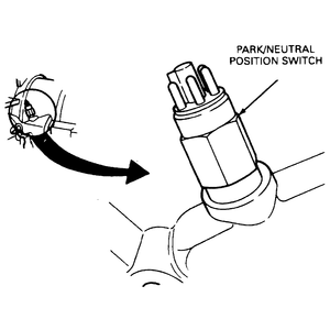
The Park/Neutral Position (PNP) switch, mounted on the transmission, allows
the vehicle to start only in P or N. The switch
has a dual purpose, in that it is also the back-up lamp switch.
| Fig. 1: View of the Park/Neutral Position (PNP) switch
used on the A4LD transmission

|
- Disconnect the negative battery cable.
- Raise and support the vehicle safely.
- Disconnect the harness connector from the neutral start switch.
- Clean the area around the switch. Remove the switch and O-ring, using a
thin wall socket (tool T74P-77247-A or equivalent).
To install:
- Fit a new O-ring to the switch. Install the switch.
- Reconnect the harness connector to the switch.
- Lower the vehicle.
- Reconnect the negative battery cable.
- Check the operation of the switch, with the parking brake engaged. The engine
should only start in N or P. The back-up lamps
should come ON only in R.
Starting in 1995, the switch was used not only for neutral start sensing and
back-up light activation, but also as a gear position range sensor. The Powertrain
Control Module reads the sensor to determine which gear position the transmission
is in, and adjusts fuel and spark timing accordingly. The new switch is called
the Transmission Range (TR) sensor.
NOTE: To install the Transmission Range (TR) sensor requires
a special Transmission Range Sensor Alignment Tool T97L-70010-AH, or equivalent.
- Disconnect the negative battery cable, block the rear wheels and apply the
parking brake.
- Place the transmission shift lever in the Neutral (N) position.
- Raise and safely support the front of the vehicle
- Disconnect the shift control cable from the transmission manual control
lever.
- Disconnect the electrical wire harness plug from the TR sensor.
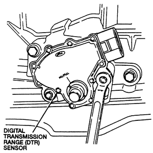
| Fig. 2: Remove the two Transmission Range (TR) sensor
retaining bolts

|
- Remove the manual control lever retaining nut as well as the lever.
- Remove the two retaining bolts and the sensor.
To install:
- Ensure that the transmission shift lever is in the Neutral (N) position.
- Install the TR sensor and loosely install the retaining bolts.
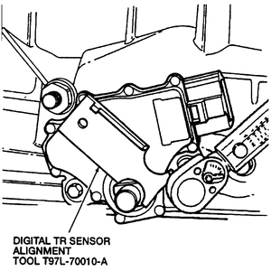
| Fig. 3: Align the new sensor with the Digital TR
Sensor Alignment Tool

|
- Align TR sensor slots using the Transmission Range Sensor Alignment Tool
T97L-70010-AH, or equivalent.
- Tighten the retaining bolts to 7–9 ft. lbs. (9–12 Nm).
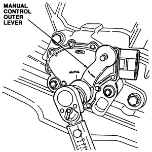
| Fig. 4: Install the manual control lever to the sensor
and tighten the retaining bolt

|
- Install the manual control lever to the sensor and tighten the retaining
nut to 22–26 ft. lbs. (30–35 Nm).
- Connect the TR sensor electrical wire harness plug.
- Install the shift control cable to the transmission manual control lever.
- Lower the vehicle and connect the negative battery cable.
- Ensure that the wheels are still blocked and the parking brake is applied.
- Check for proper operation of the switch. The engine should only start in
Park (P) or Neutral (N).
- Disconnect the negative battery cable.
- Raise and safely support the vehicle.
- Disconnect the control linkage from the transmission manual shaft.
- Disconnect the park/neutral switch harness connector, remove the switch
mounting bolts, and remove the park/neutral switch.
To install:
- Install the park/neutral switch over the manual shaft.
- Install the switch mounting bolts but do not tighten.
- Make sure the transmission manual shaft lever is positioned at the L position
(fully forward). Turn the manual shaft lever fully rearward, then return it
2 notches ( N position).
- Insert a 0.157 inch (4.0mm) pin through the holes of the switch and the
manual shaft lever.
- Tighten the switch mounting bolts to 22–35 inch lbs. (2.5–3.9
Nm). Remove the pin.
- Connect the electrical connector.
- Reinstall the shift control linkage.
- Safely lower the vehicle, connect the negative battery cable, and check
for proper operation.
- Disconnect the negative battery cable.
- Raise and safely support the vehicle.
- Disconnect the control linkage from the transmission manual shaft.
- Disconnect the wiring harness connector and remove the park/neutral switch
mounting bolts. Remove the switch from the manual shaft lever.
To install:
- Position the park/neutral switch over the manual shaft lever and install
the mounting bolts. Do not fully tighten the mounting bolts.
- Move the manual shaft lever to the N position.
- Remove the screw on the switch body and move the switch so the screw hole
is aligned with the small hole inside the switch. Check their alignment by
inserting a 0.079 in. (2.0mm) diameter pin through the holes.
- Tighten the switch mounting bolts to 43–61 inch lbs. (4.9–6.9
Nm).
- Install the screw in the park/neutral switch body and reconnect the wiring
harness connector.
- Reinstall the control linkage.
- Safely lower the vehicle, connect the negative battery cable, and check
for proper operation.

