Previous Next

Rear Driveshaft and U-Joints

REMOVAL & INSTALLATION

Navajo and B Series Pick-up Models

Fig. 1: Rear driveshaft — single & double cardan type

Fig. 2: Rear driveshaft — single cardan type

  1. Raise and safely support the vehicle.
  2. Mark the driveshaft in relation to the rear axle flange. If necessary, mark the relation of the driveshaft to the transfer case flange.
  3. If equipped with a center bearing assembly, remove the retaining bolts and the spacers under the center bearing bracket, if installed.
  4. Remove the attaching bolts and disconnect the driveshaft from the rear axle flange.
  5. On 2WD models, slide the driveshaft rearward until the slip yoke clears the transmission extension housing and remove the driveshaft. Plug the extension housing to prevent fluid leakage.
  6. On 4WD models, remove the bolts attaching the driveshaft to the transfer case flange and remove the driveshaft.

    To install:

  7. On 2WD models, lubricate the splines of the slip yoke. Remove the plug from the extension housing and install the driveshaft assembly. Do not allow the slip yoke to bottom on the output shaft with excessive force.
  8. On 4WD models, install the driveshaft to the transfer case flange, aligning the marks that were made during removal. Install the attaching bolts and tighten to 61–87 ft. lbs. (83–118 Nm) if equipped with constant velocity U-joints or 12–16 ft. lbs. (17–22 Nm) if equipped with double cardan U-joints.
  9. Connect the driveshaft to the rear axle flange, aligning the marks that were made during removal. Install the retaining bolts and tighten to 70–95 ft. lbs. (95–129 Nm).
  10. If equipped, install the center bearing attachment bolts and tighten to 27–37 ft. lbs. (37–50 Nm). Make sure the center bearing bracket is installed "square" to the vehicle. If spacers were installed under the center bearing bracket, make sure they are reinstalled.
  11. Lower the vehicle.
MPV Models

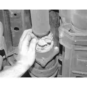
Fig. 3: Stuff a rag into the CV U-joint to hold the driveshaft straight and prevent damage to the boot

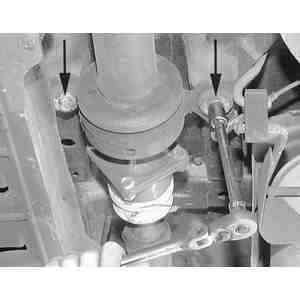
Fig. 4: Before removing any mounting nuts, matchmark the position of the driveshaft to the differential for correct reassembly

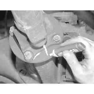
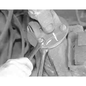
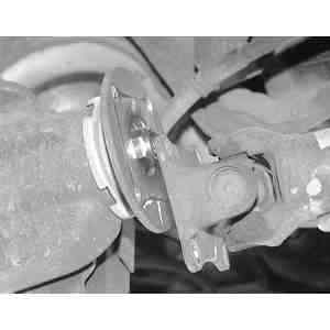
Fig. 5: To separate the driveshaft from the differential housing, use two, 14 mm box wrenches and remove the four mounting nuts

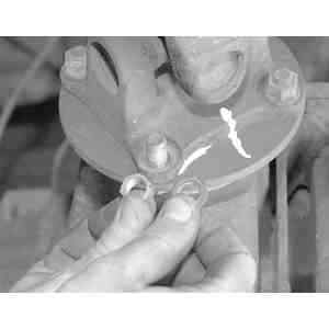
Fig. 6: Be careful not to lose the washer when removing the driveshaft-to-differential mounting nuts

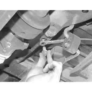
Fig. 7: Using a 14mm socket, loosen the ground wire retaining bolt . . .

  1. Raise and safely support the vehicle.
  2. Stuff a rag into the CV U-joint to hold the driveshaft straight and prevent damage to the boot.
  3. Matchmark the flanges and remove the mounting nuts and bolts at the differential.

    Fig. 8: . . . then remove the bolt, separating the ground wire from the driveshaft center bearing

    Fig. 9: Remove the driveshaft center bearing mounting bolts

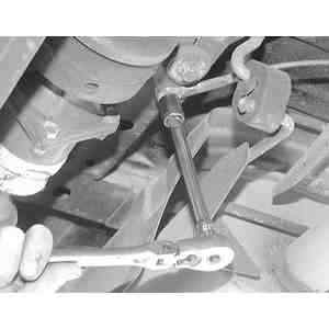
    Fig. 10: After removing the center bearing mounting bolts, separate the driveshaft from the differntial housing . . .

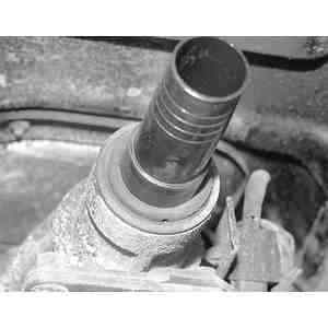
    Fig. 11: . . . then, while supporting the driveshaft assembly, slide the driveshaft straight out of the extension housing

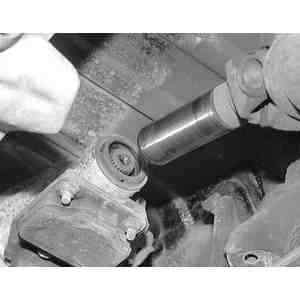
    Fig. 12: After removing the driveshaft, install a plug such as the one pictured, into the opening of the extension housing to prevent transmission fluid from dripping out

  4. Remove the bolts at the center bearing support assembly.
  5. If rear wheel drive only, remove the driveshaft from the transmission. If equipped with 4WD, remove the driveshaft from the transfer case. Cap the opening to prevent spillage of fluid.
  6. Installation is the reverse of removal. Align the flange marks when installing. Torque the mounting bolts at the differential to 37–43 ft. lbs. (50–58 Nm). Torque the bolts for the center support to 27–39 ft. lbs. (37–53 Nm).

Previous Next