
- Loosen the front wheel lug nuts.
- Raise and support the vehicle safely. Remove the wheel and tire assembly.
- Remove the disc brake calipers and support the caliper on the vehicle's
frame rail.
- Remove the hub locks and lock nuts.
- Remove the hub and rotor.
- Remove the nuts retaining the spindle to the steering knuckle. Tap the spindle
with a plastic or rawhide hammer to jar the spindle from the knuckle.
- Inspect the needle bearings inside the spindle bore. If worn or damaged,
replace as follows:
- Place the spindle in a vise on the second step of the spindle. Wrap
a shop towel around the spindle or use a brass–jawed vise to protect
the spindle.
- Remove the oil seal and needle bearing from the spindle with a slide
hammer and seal remover tool, 1175–AC or equivalent.
- Clean all dirt and grease from the spindle bearing bore. Bearing bore
must be free from nicks and burrs.
- Place the bearing in the bore with the manufacturer's identification
facing outward. Drive the bearing into the bore using spindle bearing
replacer tool, T83T–3123–A and drive handle T80T–4000–W
or equivalent.
- Install the grease seal in the bearing bore with the lip side of the
seal facing towards the tool. Drive the seal in the bore using spindle
bearing replacer tool, T83T–3123–A and drive handle T80T–4000–W
or equivalent. Coat the bearing seal lip with Multi–Purpose Long
Life Lubricant C1AZ–19590–B or equivalent.
To install:
- Inspect the seal on the axle shaft, and if damaged or worn replace it. Refer
to front axle shaft removal & installation procedure in this Section.
- Install the splash shield and spindle onto the steering knuckle. Install
and tighten the spindle nuts to 35–45 ft. lbs. (47–61Nm).
NOTE: Since the rotor is removed, check that the wheel
bearings are properly greased and that the rotor grease seal is in acceptable
condition.
- Install the rotor on the spindle.
- Install the wheel bearing, locknut, thrust bearing, snapring and locking
hubs.
- Install the disc brake calipers. Install the wheel and tire assembly.
- Lower the vehicle. Tighten the lug nuts to specification.
The 1998 B Series Pick-up models do not use spindles. Instead they use an internally
splined wheel hub which is pressed into a sealed bearing. If the assembly goes
bad, it must be replaced as an entire unit. For removal & installation procedures,
refer to Section 8.
- Raise and safely support the vehicle. Remove the wheel and tire assembly.
- Remove and discard the locknut from the end of the halfshaft.
- Remove the brake caliper and disc brake rotor. Support the caliper aside
with rope or mechanics wire; do not let the caliper hang by the brake hose.
- Remove the cotter pin and nut and, using a suitable tool, disconnect the
tie rod end from the knuckle.
- Remove the cotter pin and loosen the lower ball joint nut. Separate the
lower arm from the knuckle using a suitable tool.
- Remove the knuckle-to-strut bolts and nuts and remove the knuckle/hub assembly
from the vehicle.
- Pry out the inner oil seal from the knuckle.
- Position the knuckle/hub assembly in a press and, using a suitable driver,
press the hub from the knuckle.
NOTE: If the inner bearing race remains on the hub, position
the hub in a vise, secured by the flange. Move the race away from the hub
using a hammer and chisel, then position the hub in a press and press the
race off of the hub.
- Pry out the outer oil seal from the knuckle.
- Remove the retaining ring and position the knuckle in a press. Using a suitable
driver, press the wheel bearing from the knuckle.
- If necessary, mark the position of the dust shield on the knuckle and remove
the dust shield, using a hammer and chisel. Do not reuse the dust cover, if
removed.
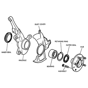
| Fig. 1: Front wheel hub, knuckle and bearing assembly — 4WD
MPV

|
To install:
- If the dust cover was removed, mark the new cover in the same place as the
old was marked during removal. Align the cover and knuckle marks and press
the cover onto the knuckle.
- Press a new wheel bearing into the knuckle, using a suitable driver. Install
the retaining ring and a new outer seal. Apply grease to the seal lip.
- Press the hub into the knuckle, using a suitable driver. Install a new inner
seal and lubricate the seal lip with grease.
- Install the knuckle/hub assembly onto the strut, install the bolts and nuts
and tighten to 69–86 ft. lbs. (93–117 Nm).
- Install the lower ball joint into the knuckle and tighten the nut to 115–137
ft. lbs. (157–187 Nm). Install a new cotter pin.
- Connect the tie rod to the knuckle and install the nut. Tighten to 43–58
ft. lbs. (59–78 Nm) and install a new cotter pin.
- Install the brake rotor and caliper.
- Install a new locknut on the end of the halfshaft and tighten to 174–231
ft. lbs. (235–314 Nm). After tightening, stake the nut with a blunt
chisel.
- Install the wheel and tire assembly and lower the vehicle. Check the front
end alignment.


