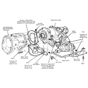
| Fig. 1: Exploded view of the 13-54 mechanical shift transfer
case

|
| Fig. 2: Exploded view of the 13-54 electronic shift transfer
case

|
CAUTION
The catalytic converter is located beside the transfer case. Be careful when
working around the catalytic converter because of the extremely high temperatures
generated by the converter.
- Disconnect the negative battery cable.
- Raise the vehicle and support it safely.
- If so equipped, remove the skid plate from frame.
- Drain the transfer case.
- Remove the damper from the transfer case, if so equipped.
- On electronic shift models, remove the wire connector from the feed wire
harness at the rear of the transfer case. Be sure to squeeze the locking tabs,
then pull the connectors apart.
- Disconnect the front driveshaft from the axle input yoke.
- If equipped, loosen the clamp retaining the front driveshaft boot to the
transfer case, and pull the driveshaft and front boot assembly out of the
transfer case front output shaft.
- Disconnect the rear driveshaft from the transfer case output shaft yoke.
- If equipped, disconnect the speedometer driven gear from the transfer case
rear cover.
- If equipped, disconnect the electrical wire harness plug from the Vehicle
Speed Sensor (VSS).
- Disconnect the vent hose from the mounting bracket.
- On manual shift models, perform the following:
- Remove the shift lever retaining nut and remove the lever.
- Remove the bolts that retains the shifter to the extension housing.
Note the size and location of the bolts to aid during installation. Remove
the lever assembly and bushing.
- If equipped, remove the heat shield from the transfer case.
- Support the transfer case with a transmission jack.
- Remove the mounting bolts retaining the transfer case to the transmission.
- Slide the transfer case rearward off the transmission output shaft and lower
the transfer case from the vehicle. Remove the gasket or any old sealer from
between the transfer case and the transmission.
To install:
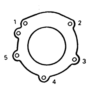
| Fig. 3: Case-to-extension bolt torque sequence — Navajo
and B Series Pick-up

|
- Install the heat shield onto the transfer case, if equipped, and place a
new gasket or silicone sealer between the transfer case and adapter.
- Raise the transfer case with a suitable transmission jack or equivalent,
raise it high enough so that the transmission output shaft aligns with the
splined transfer case input shaft.
- Slide the transfer case forward on to the transmission output shaft and
onto the dowel pin. Install transfer case retaining bolts and torque them
to specification. Tighten the mounting bolts to 35–46 ft. lbs. (47–63
Nm) on Navajo/B Series Pick-ups and 27–39 ft. lbs. (37–52 Nm)
on MPVmodels.
- The remainder of the installation procedure is the reverse of removal. Check
the fluid level and, if necessary, top off with the correct amount and type
of transfer case fluid.


