Previous Next

Transmission Assembly

REMOVAL & INSTALLATION

Fig. 1: Cutaway view of the 2 wheel drive A4LD automatic overdrive transmission

  1. Disconnect the negative battery cable.
  2. Raise the vehicle and support it safely.
  3. Position a drain pan under the transmission pan and drain the transmission fluid.
  4. Remove the converter access cover from the lower right side of the converter housing on the 3.0L engine. Remove the cover from the bottom of the engine oil pan on the 2.3L engine. Remove a bolt on the access cover of the 2.9L engine and swing the cover open. Remove the access cover and adapter plate bolts from the lower left side of the converter housing on all other applications.

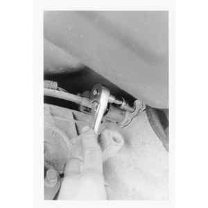
    Fig. 2: Torque converter nut access hole

  5. Remove the flywheel to converter attaching nuts. Use a socket and breaker bar on the crankshaft pulley attaching bolt. Rotate the pulley clockwise as viewed from the front to gain access to each of the nuts.

    NOTE: On belt driven overhead cam engines, never rotate the pulley in a counterclockwise direction as viewed from the front. Remove the Vehicle Speed Sensor (VSS) clamp retaining bolt . . .

    . . . then pull the VSS sensor from the transfer case (4WD) or extension housing (2WD)

  6. Remove the speedometer cable and/or vehicle speed sensor from the transfer case (4WD) or extension housing (2WD).
  7. On 2WD vehicles, scribe a mark indexing the driveshaft to the rear axle flange. Remove the driveshaft.
  8. On 4WD vehicles, remove the transfer case.

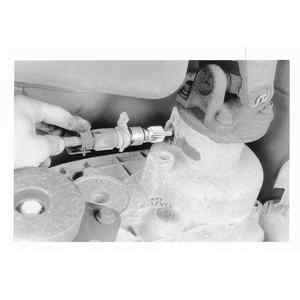
    Fig. 3: Speedometer cable connection

  9. Disconnect the shift rod or cable at the transmission manual lever and retainer bracket.
  10. Disconnect the downshift cable from the downshift lever. Depress the tab on the retainer and remove the kickdown cable from the bracket.
  11. Disconnect all of the transmission wire harness plugs.
  12. Remove the starter mounting bolts and the ground cable. Remove the starter.
  13. If equipped, remove the vacuum line from the transmission vacuum modulator.
  14. Remove the filler tube from the transmission.
  15. Position a transmission jack under the transmission and raise it slightly.
  16. Remove the engine rear support to crossmember bolts.
  17. Remove the crossmember to frame side support attaching nuts and bolts. Remove the crossmember.
  18. Remove the converter housing to engine bolts.
  19. Slightly lower the jack to gain access to the oil cooler lines. Disconnect the oil cooler lines at the transmission. Plug all openings to keep dirt and contamination out.
  20. Move the transmission to the rear so it disengages from the dowel pins and the converter is disengaged from the flywheel. Lower the transmission from the vehicle.
  21. If necessary, remove the torque converter from the transmission.

    NOTE: If the transmission is to be removed for a period of time, support the engine with a safety stand and wood block.

    To install:

    WARNING
    Before installing an automatic transmission, always check that the torque converter is fully seated into the transmission. Typically, the converter has notches or tangs on the hub which must engage the transmission fluid pump. If they are not engaged in the pump, the transmission will not mate to the engine properly, as the converter will be holding it away. Severe damage to the pump, converter or transmission casing can occur if the transmission-to-engine bolts are tightened as if to force the transmission to mate to the engine.

    Proper installation of the converter requires full engagement of the converter hub in the pump gear. To accomplish this, the converter must be pushed and at the same time rotated through what feels like 2 notches or bumps. When fully installed, rotation of the converter will usually result in a clicking noise heard, caused by the converter surface touching the housing to case bolts.

    Fig. 4: Lightly lubricate the converter hub with transmission fluid. Note the machined fluid pump drive flat on the very edge of the hub (arrow)

    Fig. 5: Handles which thread onto the converter-to-flywheel studs can be use to ease the installation process

    Fig. 6: Check dimension A to ensure that the converter is fully seated into the transmission and pump

    This should not be a concern, but an indication of proper converter installation since, when the converter is attached to the engine flywheel, it will be pulled slightly forward away from the bolt heads. Besides the clicking sound, the converter should rotate freely with no binding.

    For reference, a properly installed converter will have a distance from the converter pilot nose from face to converter housing outer face of 1332 – 916 in. (10.5–14.5mm).

  22. Install the converter on the transmission.
  23. With the converter properly installed, position the transmission on the jack.
  24. Rotate the converter so that the drive studs are in alignment with the holes in the flywheel.
  25. Move the converter and transmission assembly forward into position, being careful not to damage the flywheel and converter pilot. The converter housing is piloted into position by the dowels in the rear of the engine block.

    NOTE: During this move, to avoid damage, do not allow the transmission to get into a nose down position as this will cause the converter to move forward and disengage from the pump gear.

  26. Install the converter housing to engine attaching bolts and tighten to specification. The 2 longer bolts are located at the dowel holes.
  27. Remove the jack supporting the engine.
  28. The rest of the installation procedure is the reverse of removal. Tighten all fasteners to the following specifications:

    Navajo and B Series Pick-up Models

    MPV Models

  29. Follow the procedures outlined in Section 1 when filling the transmission with fluid.

Previous Next