- Disconnect the negative battery cable. Remove the steering wheel.
- On vehicles equipped with tilt wheel, remove the tilt lever.
- On vehicles equipped with tilt wheel, remove the steering column collar
by pressing on the collar from the top and bottom while removing the collar.
| Fig. 1: To remove the tilt column control lever,
simply rotate it counterclockwise until removed
|
- Remove the instrument panel trim cover retaining screws. Remove the trim
cover.
- Remove the 2 screws from the bottom of the steering column shroud. Remove
the bottom half of the shroud by pulling the shroud down and toward the rear
of the vehicle.
- If the vehicle is equipped with automatic transmission, move the shift lever
as required to aid in removal of the shroud. Lift the top half of the shroud
from the column.
- Remove the 2 self tapping screws that retain the combination switch to the
steering column casting. Disengage the switch from the casting.
- Disconnect the 3 electrical connectors, using caution not to damage the
locking tabs. Be sure not to damage the PRNDL cable.
- Installation is the reverse of the removal procedure. Torque the combination
switch retaining screws to 18–27 inch lbs. (2–3 Nm).
| Fig. 2: Exploded view of the combination switch mounting
and column related wire harness connectors
|
CAUTION
The air bag system must be disarmed before removing the steering wheel. Failure
to do so may cause accidental deployment, property damage or personal injury.
CAUTION
Always carry an air bag assembly with the bag and trim cover away from your
body. Store the assembly facing upward; never place the assembly face down on
any surface.
| Fig. 3: Combination switch exploded view — 1994–95
MPV
|
- Disconnect the battery.
- Remove the steering wheel.
- Remove the attaching screws, and remove the upper and lower steering column
covers.
- Disconnect the electrical connectors.
- Remove the combination retaining screw, and remove the switch.
To install:
- Install the combination switch and secure with the retaining screw.
- Connect all combination switch connectors.
- Install the steering column covers with retaining screws.
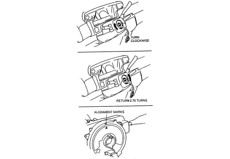
| Fig. 4: Steering column clock spring and connector
|
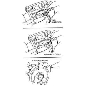
- Make sure the front wheels are aligned straight ahead and set the clock
spring connector by turning it clockwise until it stops, then return the connector
2 3⁄4 turns.
Align the marks on the clock spring connector and the outer housing.
- Install the steering wheel.
- Connect the negative battery cable.
- Check all the functions of the combination switch for proper operation.
CAUTION
The air bag system must be disarmed before removing the steering wheel. Failure
to do so may cause accidental deployment, property damage or personal injury.
CAUTION
Always carry an air bag assembly with the bag and trim cover away from your
body. Store the assembly facing upward; never place the assembly face down on
any surface.
- Disconnect the negative battery cable and wait at least 90 seconds before
performing any work.
- Remove the service caps and remove the bolts securing the air bag module
to the steering wheel. Disconnect the air bag connector and remove the air
bag module.
- Remove the steering wheel nut and remove the steering wheel.
- Remove the screws and the upper and lower steering column covers.
- Disconnect the clock spring connector, remove the mounting screws, and remove
the clock spring.
- Disconnect the combination switch connector, remove the mounting screws
and remove the combination switch.
| Fig. 5: Combination switch and components — 1996–98
MPV
|
To install:
- Install the combination switch with the mounting screws and reconnect the
connector.
- Install the clock spring with its screws and reconnect the connector. The
clock spring must be adjusted in the following manner:
- Turn the clock spring clockwise until it stops.
- Turn the clock spring counterclockwise 2 3⁄4 turns.
- Align the marks on the clock spring connector with that on the outer
housing.
- Reinstall the steering column upper and lower covers with the mounting screws.
- Reinstall the steering wheel and tighten with the nut.
- Reconnect the air bag module connector and install the air bag with its
mounting bolts. Reinstall the service caps.
- Reconnect the negative battery cable and check for proper operation.