- Raise and support the vehicle safely. Remove the tire and wheel assembly
from the hub and rotor.
- Remove the caliper from its mounting and position it to the side with mechanics
wire in order to prevent damage to the brake line hose.
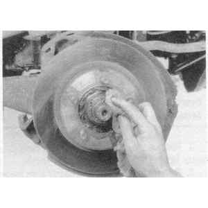
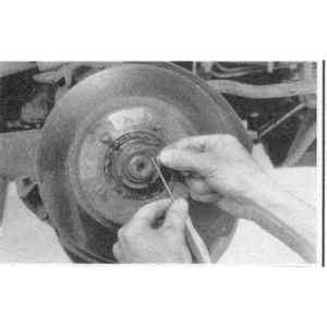
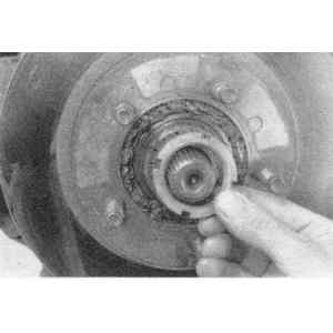
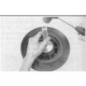
- Remove the grease cap from the hub. Remove the cotter pin, retainer, adjusting
nut and flatwasher from the spindle.
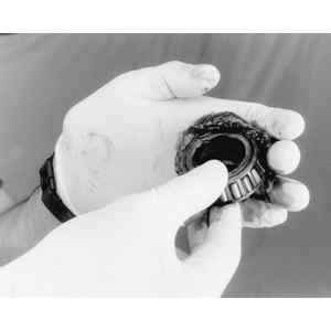
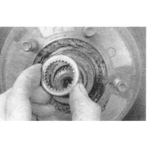
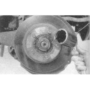
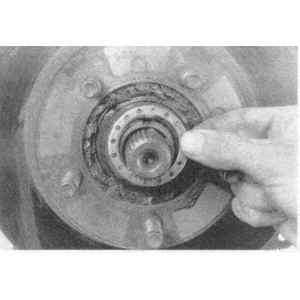
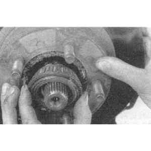
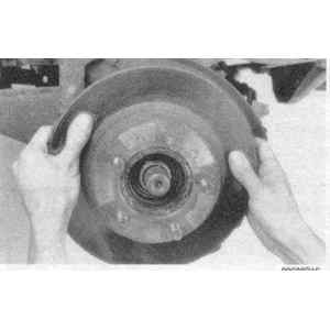
- Remove the outer bearing cone and roller assembly from the hub. Remove the
hub and rotor from the spindle.
| Fig. 1: Remove the nut and washer from the spindle
. . .

|
| Fig. 2: . . . then remove the outer bearing

|
| Fig. 3: Pull the hub and rotor assembly from the
spindle
|
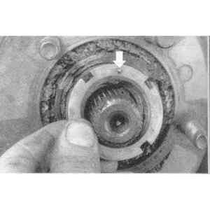
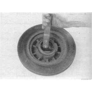
- Using seal removal tool 1175-AC or equivalent remove and discard the grease
seal. Remove the inner bearing cone and roller assembly from the hub.
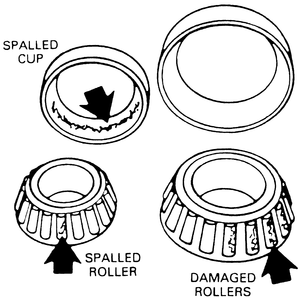
- Clean the inner and outer bearing assemblies in solvent. Inspect the bearings
and the cones for wear and damage. Replace defective parts, as required.
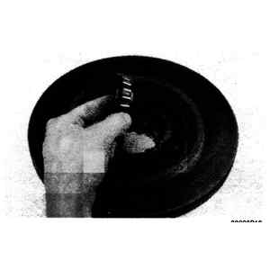
| Fig. 5: With the seal removed, the inner bearing
may be withdrawn from the hub
|
- If the cups are worn or damaged, remove them with front hub remover tool
T81P-1104-C and tool T77F-1102-A or equivalent.
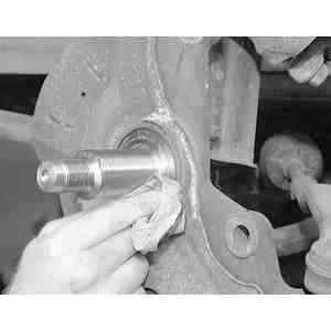
- Wipe the old grease from the spindle. Check the spindle for excessive wear
or damage. Replace defective parts, as required.
To install:
- If the inner and outer cups were removed, use bearing driver handle tool
T80-4000-W or equivalent and replace the cups. Be sure to seat the cups properly
in the hub.
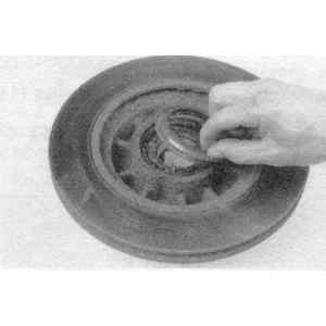
- Use a bearing packer tool and properly repack the wheel bearings with the
proper grade and type grease. If a bearing packer is not available work as
much of the grease as possible between the rollers and cages. Also, grease
the cone surfaces.
| Fig. 6: Thoroughly pack the bearing with fresh, high
temperature wheel bearing grease
|
- Position the inner bearing cone and roller assembly in the inner cup. A
light film of grease should be included between the lips of the new grease
retainer (seal).
- Install the retainer using the proper installer tool. Be sure that the retainer
is properly seated.
| Fig. 7: Apply a thin coat of fresh grease to the
new seal lip
|
| Fig. 8: Use a suitably sized driver to install the
inner bearing seal to the hub
|
- Install the hub and rotor assembly onto the spindle. Keep the hub centered
on the spindle to prevent damage to the spindle and the retainer.
- Install the outer bearing cone and roller assembly and flatwasher on the
spindle. Install the adjusting nut. Adjust the wheel bearings.
- Install the retainer, a new cotter pin and the grease cap. Install the caliper.
- Lower the vehicle and tighten the lug nuts to 100 ft. lbs. Before driving
the vehicle pump the brake pedal several times to restore normal brake pedal
travel.
CAUTION
Retighten the wheel lug nuts to specification after about 500 miles of driving.
Failure to do this could result in the wheel coming off while the vehicle
is in motion possibly causing loss of vehicle control or collision.
| Fig. 9: Inspect the bearings for abnormal wear and/or
damage
|
- Raise the vehicle and install jackstands.
- Remove the wheel and tire assembly.
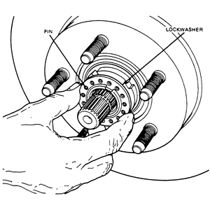
- Remove the retainer washers from the lug nut studs and remove the manual
locking hub assembly from the spindle.
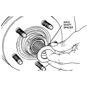
- Remove the snapring and spacer from the end of the spindle shaft.
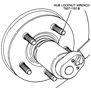
- Remove the outer wheel bearing locknut from the spindle using 4 prong spindle
nut spanner wrench, T86T-1197-A or equivalent. Make sure the tabs on the tool
engage the slots in the locknut.
- Remove the locknut washer from the spindle.
- Remove the inner wheel bearing locknut from the spindle using 4 prong spindle
nut spanner wrench, T86T-1197-A or equivalent. Make sure the tabs on the tool
engage the slots in the locknut.
- Remove the outer bearing cone and roller assembly from the hub. Remove the
hub and rotor from the spindle.
- Using seal removal tool 1175-AC or equivalent remove and discard the grease
seal. Remove the inner bearing cone and roller assembly from the hub.
- Clean the inner and outer bearing assemblies in solvent. Inspect the bearings
and the cones for wear and damage. Replace defective parts, as required.
- If the cups are worn or damaged, remove them with front hub remover tool
T81P-1104-C and tool T77F-1102-A or equivalent.
- Wipe the old grease from the spindle. Check the spindle for excessive wear
or damage. Replace defective parts, as required.
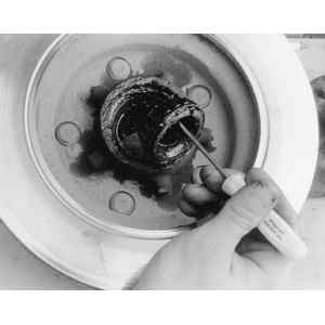
| Fig. 10: Before beginning the wheel bearing removal,
and after the outer hub is removed, wipe off any excess grease
|
| Fig. 11: After the grease is wiped off, remove the
axle shaft snapring . . .
|
| Fig. 12: . . . then pull the splined spacer from
the axle shaft end
|
| Fig. 13: Use a 4 pronged socket to loosen the outer
wheel bearing locknut . . .
|
| Fig. 14: . . . then remove the outer locknut
|
| Fig. 15: Remove the lockwasher from behind the outer
locknut . . .
|
| Fig. 16: . . . then loosen and remove the inner locknut — note
the lockwasher engagement pin (arrow)
|
| Fig. 17: While pushing inwards on the rotor/hub assembly,
remove the outer wheel bearing . . .
|
| Fig. 18: . . . then pull the rotor/hub assembly from
the spindle, taking care not to scratch the bearing cups in the hub
|
| Fig. 19: Pry out the grease seal on the back of the
rotor/hub assembly . . .
|
| Fig. 20: . . . then remove the inner wheel bearing.
Thoroughly clean and inspect all of the parts for wear or damage
|
To install:
- If the inner and outer cups were removed, use bearing driver handle tool
T80-4000-W or equivalent and replace the cups. Be sure to seat the cups properly
in the hub.
- Use a bearing packer tool and properly repack the wheel bearings with the
proper grade and type grease. If a bearing packer is not available work as
much of the grease as possible between the rollers and cages. Also, grease
the cone surfaces.
- Position the inner bearing cone and roller assembly in the inner cup. A
light film of grease should be included between the lips of the new grease
seal.
- Install the grease seal by driving in place with hub seal replacer tool
T83T-1175-B and Driver Handle T80T-4000-W.
- Install the hub and rotor assembly onto the spindle. Keep the hub centered
on the spindle to prevent damage to the spindle and the retainer.
- Install the outer bearing cone and roller assembly
- Carefully install the rotor onto the spindle. Install the outer wheel bearing
in the rotor.
- Install the inner adjusting nut with the pin facing out. Tighten the inner
adjusting nut to 35 ft. lbs. (47 Nm) to seat the bearings.
- Follow the appropriate wheel bearing adjustment procedures.
| Fig. 21: After packing the bearing with grease, position
a new seal to the rotor/hub assembly . . .
|
| Fig. 22: . . . then, using the correct seal installer,
drive the seal into the rotor/hub until it is fully seated
|
| Fig. 23: Ensure that the pin on the inner locknut
engages one of the holes of the lock washer
|
| Fig. 24: Tighten the outer wheel bearing locknut
to specification
|
| Fig. 25: Install the splined axle shaft spacer then
the snapring
|
- Raise the vehicle and install jackstands.
- Remove the wheel and tire assembly.
- Remove the retainer washers from the lug nut studs and remove the automatic
locking hub assembly from the spindle.
- Remove the snapring and spacer from the end of the spindle shaft.
| Fig. 26: Exploded view of the locking cam, thrust
washers, locking key and bearing adjuster nut
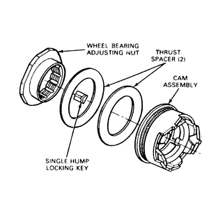
|
| Fig. 27: Remove the wheel bearing adjusting nut after
removing the locking key from under it
|
- Pull the locking cam assembly and the two plastic spacers off of the wheel
bearing adjusting nut.
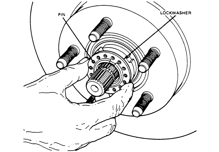
- Use a magnet and remove the locking key from under the adjusting nut. If
required, rotate the adjusting nut slightly to relieve pressure against the
locking key.
WARNING
To prevent damage to the adjusting nut and spindle threads on vehicles equipped
with automatic hubs, look into the spindle keyway under the adjusting nut
and remove the separate locking key before removing the adjusting nut.
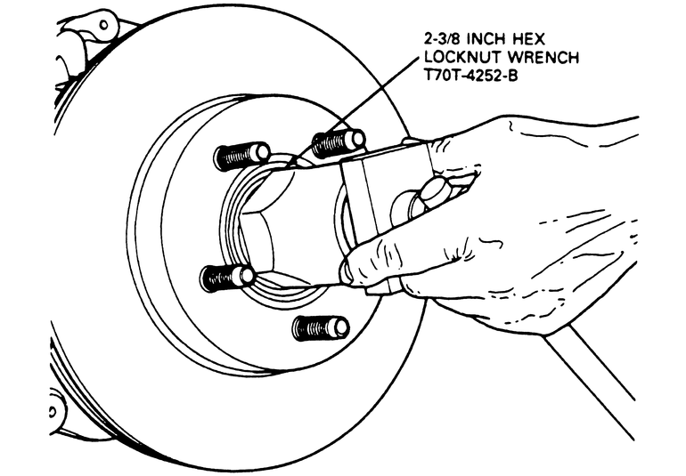
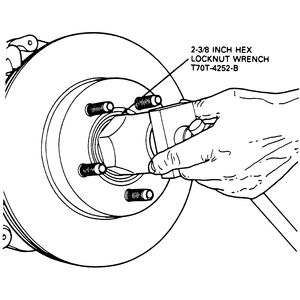
- Remove the wheel bearing locknut using a 2- 3⁄8 inch
(60.3mm) hex socket, such as Hex Locknut Wrench T70T-4252-B.
- Remove the outer bearing cone and roller assembly from the hub. Remove the
hub and rotor from the spindle.
- Using seal removal tool 1175-AC or equivalent remove and discard the grease
seal. Remove the inner bearing cone and roller assembly from the hub.
- Clean the inner and outer bearing assemblies in solvent. Inspect the bearings
and the cones for wear and damage. Replace defective parts, as required.
- If the cups are worn or damaged, remove them with front hub remover tool
T81P-1104-C and tool T77F-1102-A or equivalent.
- Wipe the old grease from the spindle. Check the spindle for excessive wear
or damage. Replace defective parts, as required.
To install:
- If the inner and outer cups were removed, use bearing driver handle tool
T80-4000-W or equivalent and replace the cups. Be sure to seat the cups properly
in the hub.
- Use a bearing packer tool and properly repack the wheel bearings with the
proper grade and type grease. If a bearing packer is not available work as
much of the grease as possible between the rollers and cages. Also, grease
the cone surfaces.
- Position the inner bearing cone and roller assembly in the inner cup. A
light film of grease should be included between the lips of the new grease
seal.
- Install the grease seal by driving in place with hub seal replacer tool
T83T-1175-B and Driver Handle T80T-4000-W.
- Install the hub and rotor assembly onto the spindle. Keep the hub centered
on the spindle to prevent damage to the spindle and the retainer.
- Install the outer bearing cone and roller assembly.
- Carefully install the rotor onto the spindle. Install the outer wheel bearing
in the rotor.
- Install the adjusting nut and tighten 35 ft. lbs. (47 Nm) to seat the bearings.
- Follow the appropriate wheel bearing adjustment procedures.
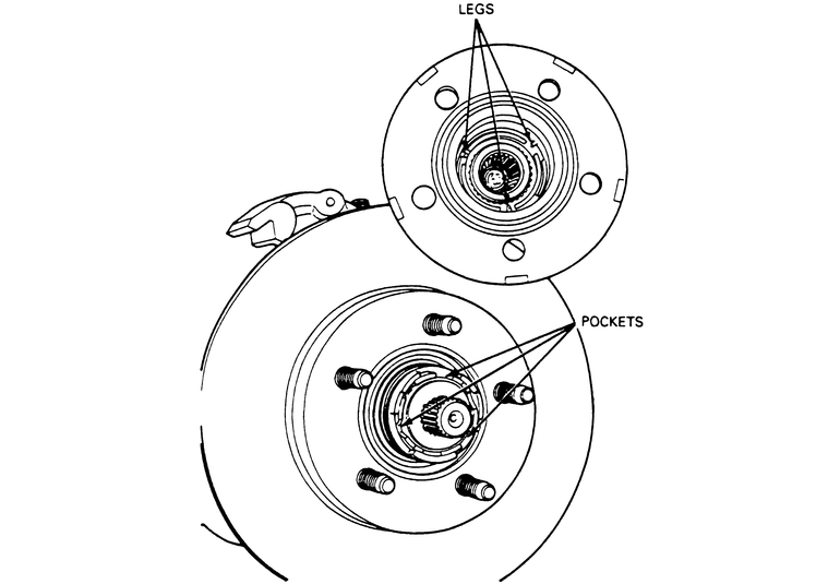
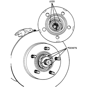
| Fig. 28: When installing the outer hub cover, align
the cam pockets with the legs on the cover
|
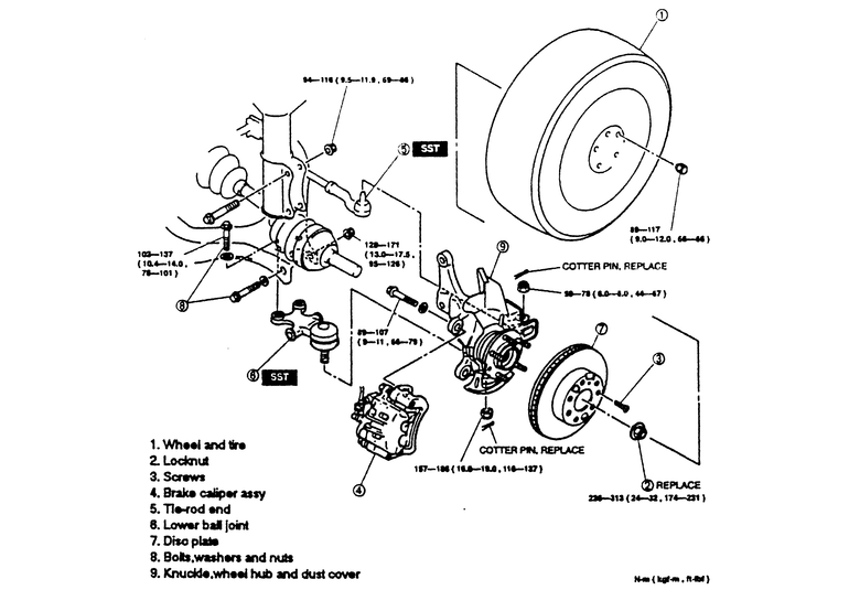
| Fig. 29: Exploded view of the Mountaineer and 1995–97
Explorer sealed front wheel bearing and related components
|
WARNING
If equipped, always turn off the Automatic Ride Control (ARC) service switch
before lifting the vehicle off of the ground. Failure to do so could damage
the ARC system components. Refer to Section 1 for jacking procedures.
- Loosen the wheel lug nuts then raise and safely support the front of the
vehicle.
- Remove the wheels.
- Remove the front disc brake caliper, bracket and rotor. Also remove the
rotor splash shield.
- If equipped, unbolt the front wheel ABS sensor and wire harness from the
steering knuckle.
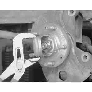
- Remove the front wheel hub nut and washer.
WARNING
Never reuse the wheel hub nut and washer. This nut is a torque prevailing
design and cannot be reused.
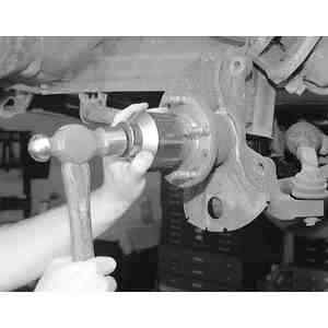
NOTE: The hub shaft is a slip fit into the wheel hub and
bearing; a press is not normally required.
- Ensure that the wheel hub shaft can be pushed inwards. If not, assemble
a press to the front wheel studs and press the wheel hub shaft inwards slightly
to break it loose.
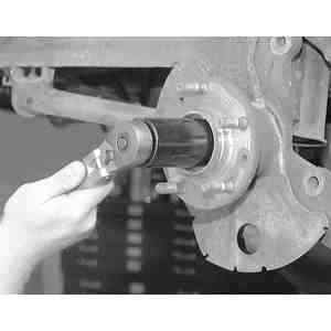
- Remove the three wheel hub/bearing to steering knuckle retaining bolts.
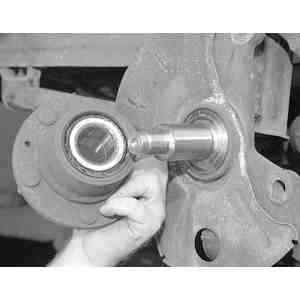
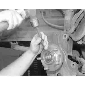
Remove the hub and bearing assembly.
To install:
- Install the ABS sensor to the wheel hub then position the hub to the front
axle shaft and steering knuckle.
- Install the three retaining bolts and tighten them to 70–80 ft. lbs.
(95–108 Nm).
- Install the hub washer and nut and tighten to 157–213 ft. lbs. (212–288
Nm).
- Install the ABS sensor retaining bolt.
- Install the front brake rotor shield, rotor, bracket and caliper.
- Install the wheel and snug the lug nuts.
- Lower the vehicle and tighten the lug nuts to 100 ft. lbs. (135 Nm).
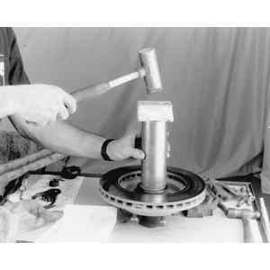
| Fig. 30: Remove the dust cap from the wheel hub, using
pliers, if necessary
|
| Fig. 31: Installing the dust cap onto the wheel hub using
a hammer and a 2 3/8 inch socket
|
| Fig. 32: If the wheel hub retaining nut was staked previously,
open it up using a hammer and a punch or drift

|
| Fig. 33: Using a 34mm deep well socket, remove the wheel
hub retaining nut
|
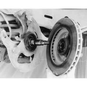
| Fig. 34: Remove the wheel hub/bearing assembly by sliding
straight off of the spindle
|
| Fig. 35: Be sure to clean the spindle area of any debris
using a towel
|
- Raise and safely support the vehicle.
- Remove the wheel assembly.
- Remove the hub dust cap.
- Remove the locknut.
- Remove the brake caliper.
- Remove the disc plate.
- Remove the hub assembly.
To install:
| Fig. 36: After installing the wheel hub/bearing assembly
and retaining nut, use a torque wrench to tighten the nut
|
| Fig. 37: Using a hammer and a punch or drift, stake
the hub/bearing retaining nut onto the spindle
|
- Install the hub assembly.
- Install the disc plate.
- Install the brake caliper, torque the mounting bolts to 66–79 ft.
lbs. (89–107 Nm).
- Install the locknut, torque to 131–173 ft. lbs. (117–235 Nm).
- Using a hammer and a punch or drift, stake the hub/bearing retaining nut
onto the spindle.
- Install the hub dust cap.
- Install the wheel assembly.
- Lower the vehicle.
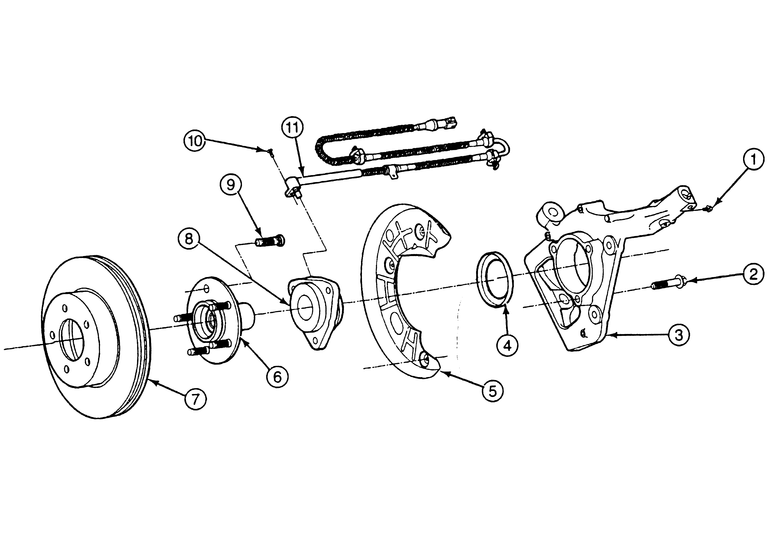
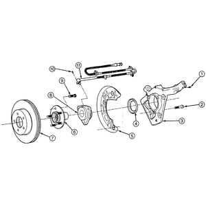
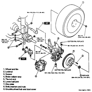
| Fig. 38: Front hub and related components, exploded view — 4WD
|
- Raise and safely support the vehicle.
- Remove the wheel assembly.
- Remove the locknut.
- Remove the brake caliper.
- Remove the disc plate retaining screw(s).
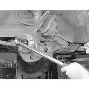
- Disconnect the tie-rod end from the knuckle.
- Disconnect the lower ball joint.
- Remove the disc plate.
- Remove the ball joint mounting nuts and bolts.
- Remove the knuckle, wheel hub and dustplate as an assembly.
- Remove the wheel hub/bearing assembly from the knuckle.
To install:
- Install wheel hub/bearing assembly to the knuckle.
- Install the knuckle assembly. Torque the strut mounting nut to 69–86
ft. lbs. (94–116 Nm).
- Install the ball joint mounting nuts and bolts. Torque the upper mounting
bolts to 76–101 ft. lbs. (102–137 Nm). Torque the through-bolt
nut to 95–106 ft. lbs. (128–171 Nm).
- Replace the disc plate.
- Install ball joint to the knuckle assembly. Torque the ball joint nut to
116–137 ft. lbs. (157–186 Nm).
- Connect the tie-rod end, torque the nut to 44–57 ft. lbs. (59–78
Nm).
- Install the brake caliper, torque the mounting bolts to 66–79 ft.
lbs. (89–107 Nm).
- Install the disc plate retaining nut.
- Install the locknut, torque to 174–231 ft. lbs. (236–313 Nm).
- Install the wheel assembly.
- Lower the vehicle.