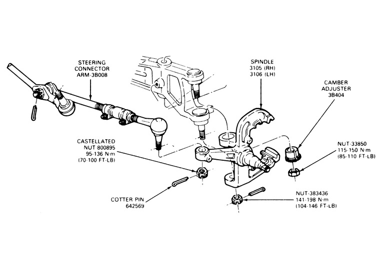
| Fig. 1: Navajo spindle removal–B Series Pick-up
similar
|
- Raise the front of the vehicle and install jackstands.
- Remove the wheel and tire assembly.
- Remove the caliper assembly from the rotor and hold it out of the way with
wire.
- Remove the dust cap, cotter pin, nut, nut retainer, washer, and outer bearing,
and remove the rotor from the spindle.
- Remove brake dust shield.
- Disconnect the steering linkage from the spindle and spindle arm by removing
the cotter pin and nut.
- With Tie Rod removal tool 3290-D or equivalent remove the tie rod end from
the spindle arm.
- If equipped, unbolt the front wheel ABS sensor and wire harness from the
steering knuckle.
- Remove the cotter pin and the castellated nut from the lower ball joint
stud.
- Remove the axle clamp bolt from the axle. Remove the camber adjuster from
the upper ball joint stud and axle beam.
- Strike the area inside the top of the axle to pop the lower ball joint loose
from the axle beam.
WARNING
Do not use a ball joint fork to separate the ball joint from the spindle,
as this will damage the seal and the ball joint socket!
- Remove the spindle and the ball joint assembly from the axle.
To install:
NOTE: A 3 step sequence for tightening ball joint stud
nuts must be followed to avoid excessive turning effort of spindle about
axle.
- Prior to assembly of the spindle, make sure the upper and lower ball joints
seals are in place.
- Place the spindle and the ball joint assembly into the axle.
- Install the camber adjuster in the upper over the upper ball joint. If camber
adjustment is necessary, special adapters must be installed.
- Tighten the lower ball joint stud to 104–146 ft. lbs. (141–198
Nm) for 1994 models and 89–133 ft. lbs. (120–180 Nm) for 1995–97
models. Continue tightening the castellated nut until it lines up with the
hole in the ball joint stud. Install the cotter pin. Install the dust shield.
- If removed, install the front wheel ABS sensor and wire harness to the steering
knuckle.
- Install the hub and rotor on the spindle.
- Install the outer bearing cone, washer, and nut. Adjust bearing end-play
and install the cotter pin and dust cap.
- Install the caliper.
- Connect the steering linkage to the spindle. Tighten the nut to 52–74
ft. lbs. (70–100 Nm) and advance the nut as required for installation
of the cotter pin.
- Install the wheel and tire assembly. Lower the vehicle. Check, and if necessary,
adjust the toe setting.
- Raise the vehicle and support on jackstands.
- Remove the wheel and tire assembly.
- Remove the caliper.
- Remove hub locks and locknuts.
- Remove the hub and rotor. Ensure that the wheel bearings do not fall out.
- Remove the nuts retaining the spindle to the steering knuckle. Tap the spindle
with a plastic or rawhide hammer to jar the spindle from the knuckle. Remove
the splash shield.
- Remove the axle shaft for the side of the vehicle you are working on. Refer
to Section 7 for axle shaft removal procedures.
- Remove the cotter pin from the tie rod nut and then remove the nut. Tap
on the tie rod stud to free it from the steering arm.
- Remove the upper ball joint cotter pin and nut. Loosen the lower ball joint
nut to the end of the stud.
- Strike the inside of the spindle near the upper and lower ball joints to
break the spindle loose from the ball joint studs.
- Remove the camber adjuster sleeve. If required, use pitman arm puller, T64P-3590-F
or equivalent to remove the adjuster out of the spindle. Remove the lower
ball joint nut.
- Remove the steering knuckle from the I-beam end.
To install:
- Install the steering knuckle to the I-beam end, engaging both upper and
lower ball joints studs in their respective holes.
- Install the camber adjuster into the support arm. Position the slot in its
original position.
CAUTION
The following torque sequence must be followed exactly when securing the
spindle. Excessive spindle turning effort may result in reduced steering
returnability if this procedure is not followed.
- Install a new nut on the bottom of the ball joint stud and torque to 90
ft. lbs. (minimum). Tighten to align the nut to the next slot in the nut with
the hole in the ball joint stud. Install a new cotter pin.
- Install the snapring on the upper ball joint stud. Install the upper ball
joint pinch bolt and torque the nut to 48–65 ft. lbs.
NOTE: The camber adjuster will seat itself into the knuckle
at a predetermined position during the tightening sequence. Do not attempt
to adjust this position.
- Install the axle shaft or shafts that were removed.
- Install the splash shield and spindle onto the steering knuckle. Install
and tighten the spindle nuts to 40–50 ft. lbs.
- Install the rotor on the spindle and push the outer wheel bearing inwards
to seat it..
- Install the locknuts and adjust the wheel bearings. Install the remainder
of the locking hub assemblies.
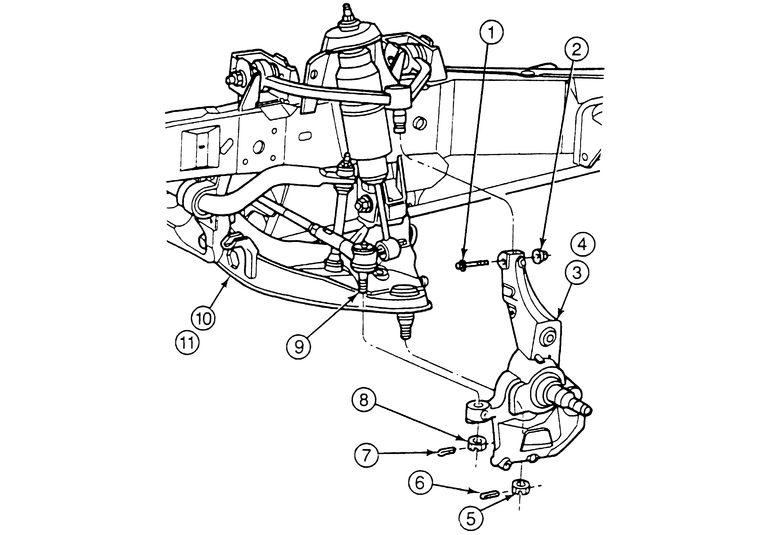
| Fig. 2: Exploded view of the 1998 B Series Pick-up steering
knuckle
|
NOTE: The steering knuckle and spindle are an integral assembly.
- Position the steering wheel to the on-center position.
- Loosen the wheel lug nuts then raise and safely support the front of the
vehicle.
- Remove the wheels.
- Remove the front disc brake caliper, bracket and rotor. Also remove the
rotor splash shield.
- Remove the cotter pin and nut retaining the tie rod end to the steering
knuckle.
- Disconnect the tie rod end from the steering knuckle using a jawed puller,
such as Pitman Arm Puller T64P-3590-F, or equivalent.
- If equipped, unbolt the front wheel ABS sensor and wire harness from the
steering knuckle.
- Support the lower control arm with a jack. Remove the cotter pin and loosen
the nut retaining the lower ball joint to the steering knuckle.
- Disconnect the lower ball joint from the steering knuckle using a jawed
puller, such as Pitman Arm Puller T64P-3590-F, or equivalent.
- Remove the lower ball joint retaining nut and slowly raise the lower control
arm until the ball joint stud is disengaged from the steering knuckle.
- Remove the upper ball joint retaining bolt and nut from the steering knuckle
then disconnect the joint from the knuckle.
- Remove the steering knuckle/spindle assembly from the vehicle.
To install:
- Inspect the upper and lower ball joints and seals for damage and replace
as needed.
- Position the steering knuckle onto the upper ball joint and install the
retaining bolt and nut. Tighten the bolt to 30–41 ft. lbs. (40–55
Nm).
- Install the lower ball joint stud into the steering knuckle until the stud
protrudes through the knuckle.
- Install the retaining nut to the lower ball joint stud and tighten to 84–113
ft. lbs. (113–153 Nm). Install the cotter pin, advancing (tightening)
the nut as needed. Never loosen the ball joint nut in order to install the
cotter pin.
- Connect the tie rod end to the steering knuckle and install the retaining
nut. Tighten to 57–77 ft. lbs. (77–104 Nm) and install the cotter
pin, advancing (tightening) the nut as needed. Never loosen the ball joint
nut in order to install the cotter pin.
- Install the front disc brake splash shield, rotor, bracket and caliper.
- Install the wheel and snug all of the lug nuts.
- Lower the vehicle and tighten the wheel lug nuts to 100 ft. lbs. (135 Nm).
WARNING
Do not perform this procedure unless a new wheel hub nut and washer assembly
is available. Once removed, these parts must never be reused during assembly.
- Position the steering wheel to the on-center position.
WARNING
If equipped, always turn off the Automatic Ride Control (ARC) service switch
before lifting the vehicle off of the ground. Failure to do so could damage
the ARC system components. Refer to Section 1 for jacking procedures.
- Loosen the wheel lug nuts then raise and safely support the front of the
vehicle.
- Remove the wheels.
- Remove the front disc brake caliper, bracket and rotor. Also remove the
rotor splash shield.
- If equipped, unbolt the front wheel ABS sensor and wire harness from the
steering knuckle.
- Remove the front wheel hub nut and washer.
WARNING
Never reuse the wheel hub nut and washer. This nut is a torque prevailing
design and cannot be reused.
- Remove the cotter pin and nut retaining the tie rod end to the steering
knuckle.
- Disconnect the tie rod end from the steering knuckle using a jawed puller,
such as Pitman Arm Puller T64P-3590-F, or equivalent.
- Unload the torsion bar. Follow the torsion bar removal procedures, but do
not remove the bar.
- Support the lower control arm with a jack. Remove the cotter pin and loosen
the nut retaining the lower ball joint to the steering knuckle.
- Disconnect the lower ball joint from the steering knuckle using a jawed
puller, such as Pitman Arm Puller T64P-3590-F, or equivalent.
- Remove the lower ball joint retaining nut and slowly raise the lower control
arm until the ball joint stud is disengaged from the steering knuckle.
NOTE: The hub shaft is a slip fit into the wheel hub and
bearing; a press is not normally required.
- Ensure that the wheel hub shaft can be pushed inwards. If not, assemble
a press to the front wheel studs and press the wheel hub shaft inwards slightly
to break it loose.
- Remove the upper ball joint retaining bolt and nut from the steering knuckle
then disconnect the joint from the knuckle.
- Remove the steering knuckle/spindle assembly from the vehicle.
To install:
- Inspect the upper and lower ball joints and seals for damage and replace
as needed.
- Position the steering knuckle onto the upper ball joint, while aligning
the axle shaft with the wheel hub, and install the retaining bolt and nut.
Tighten the bolt to 30–41 ft. lbs. (40–55 Nm).
- Install the lower ball joint stud into the steering knuckle until the stud
protrudes through the knuckle.
- Install the retaining nut to the lower ball joint stud and tighten to 84–113
ft. lbs. (113–153 Nm). Install the cotter pin, advancing (tightening)
the nut as needed. Never loosen the ball joint nut in order to install the
cotter pin.
- Connect the tie rod end to the steering knuckle and install the retaining
nut. Tighten to 57–77 ft. lbs. (77–104 Nm) and install the cotter
pin, advancing (tightening) the nut as needed. Never loosen the ball joint
nut in order to install the cotter pin.
- If removed, install the ABS sensor to the wheel hub.
- Install the hub washer and nut then tighten to 157–213 ft. lbs. (212–288
Nm).
- Install the front disc brake splash shield, rotor, bracket and caliper.
- Install the wheel and snug all of the lug nuts.
- Reload the torsion bar pressure. Refer to the torsion bar installation procedures.
Check and, if necessary, set the vehicle ride height.
- Lower the vehicle and tighten the wheel lug nuts to 100 ft. lbs. (135 Nm).
- Raise and safely support the vehicle.
- Remove the wheel assembly.
- Remove the wheel hub/bearing assembly, if necessary.
- Remove the brake caliper.
- Remove the disc plate.
- Disconnect the tie-rod end from the knuckle/spindle.
- Disconnect the lower arm.
- Remove the knuckle/spindle assembly.
To install:
- Install the knuckle/spindle assembly. Torque the strut mounting nut to 69–86
ft. lbs. (94–116 Nm).
- Install the lower arm, ball joint to the knuckle/spindle assembly. Torque
the ball joint nut to 87–115 ft. lbs. (118–156 Nm).
- Connect the tie-rod end, torque the nut to 44–57 ft. lbs. (59–78
Nm).
- Install wheel hub/bearing assembly, if removed.
- Install the disc plate.
- Install the brake caliper, torque the mounting bolts to 66–79 ft.
lbs. (89–107 Nm).
- Install the locknut, torque to 131–173 ft. lbs. (117–235 Nm).
- Install the hub dust cap.
- Install the wheel assembly.
- Lower the vehicle.
- Raise and safely support the vehicle.
- Remove the wheel assembly.
- Remove the locknut.
- Remove the brake caliper.
- Remove the disc plate retaining screw(s).
- Disconnect the tie-rod end from the knuckle.
- Disconnect the lower ball joint.
- Remove the disc plate.
- Remove the ball joint mounting nuts and bolts.
- Remove the knuckle, wheel hub and dustplate as an assembly.
- Remove the wheel bearings from the hub assembly, if needed.
To install:
- Install wheel bearings to the hub assembly, if removed.
- Install the knuckle assembly. Torque the strut mounting nut to 69–86
ft. lbs. (94–116 Nm).
- Install the ball joint mounting nuts and bolts. Torque the upper mounting
bolts to 76–101 ft. lbs. (102–137 Nm). Torque the through-bolt
nut to 95–106 ft. lbs. (128–171 Nm).
- Replace the disc plate.
- Install ball joint to the knuckle assembly. Torque the ball joint nut to
116–137 ft. lbs. (157–186 Nm).
- Connect the tie-rod end, torque the nut to 44–57 ft. lbs. (59–78
Nm).
- Install the brake caliper, torque the mounting bolts to 66–79 ft.
lbs. (89–107 Nm).
- Install the disc plate retaining nut.
- Install the locknut, torque to 174–231 ft. lbs. (236–313 Nm).
- Install the wheel assembly.
- Lower the vehicle.