WARNING
If equipped, always turn off the Automatic Ride Control (ARC) service switch
before lifting the vehicle off of the ground. Failure to do so could damage
the ARC system components. Refer to Section 1 for jacking procedures.
- Raise and safely support the front of the vehicle, block the rear wheels
and apply the parking brake.
- Start the engine then rotate the steering wheel from lock-to-lock and record
the number of rotations.
- Divide the number of rotations by two. This gives the number of rotations
to achieve true center of the steering. Turn the wheel in one direction to
the full lock.
- Turn the wheel in the opposite direction the number of turns equal to true
steering (lock-to-lock number divided by two).
WARNING
Do not rotate the steering wheel when the shaft is disconnected from the
steering gear as damage to the clock spring could occur.
- Remove the bolt retaining the lower steering column shaft to the steering
gear input shaft and disconnect the two.
- Remove the stabilizer bar.
| Fig. 1: View of the power steering hose connections
for the power rack and pinion steering gear

|
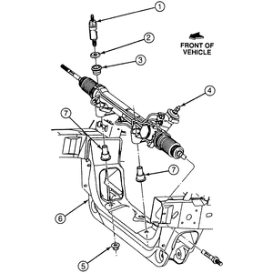
| Fig. 2: Exploded view of the power rack and pinion
steering gear mounting

|
- Unscrew the quick-connect fittings for the power steering pressure and return
hoses at the steering gear housing.
- Plug the ends of the lines and the fitting in the rack to avoid dirt contamination.
- Remove the two nuts securing the power steering cooler and remove the cooler.
- Remove the outer tie rod ends.
- Remove the two nuts, bolts and washer assemblies retaining the steering
gear housing to the front crossmember.
To install:
- Position the steering gear to the front crossmember and install the nuts,
bolts and washer assemblies. Tighten to 94–127 ft. lbs. (128–172
Nm).
- Install the power steering cooler and two retaining bolts.
- Connect the power steering lines to the steering gear housing and tighten
the fittings to 20–25 ft. lbs. (27–34 Nm).
- Install the outer tie rod ends.
- Ensure that the steering shaft or gear input shaft has not been rotated,
then connect the two.
- Install the intermediate shaft-to-steering input shaft retaining (pinch)
bolt and tighten to 30–42 ft. lbs. (41–56 Nm).
- Lower the vehicle and refill the power steering pump reservoir.
- Bleed the air from the power steering system. Follow the procedures in this
Section.
- Ensure that there are no leaks and the fluid is maintained at the proper
level.
- Have the alignment checked and adjusted by a professional repair shop.
- Place the front wheels in the straight-ahead position. Raise and safely
support the vehicle.
- Remove the wheel and tire assemblies. Remove the splash shield.
- Remove the cotter pins and nuts from both tie rod end studs. Separate the
tie rod ends from the knuckles.
- Remove the pinch bolt from the intermediate shaft-to-pinion shaft coupling.
- Disconnect and plug the pressure line from the rack and pinion assembly.
Loosen the clamp and disconnect the return line from the rack and pinion assembly.
Plug the line.
- If equipped with automatic transmission, remove the change counter assembly
to remove the protector plate mounting bolt.
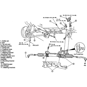
- Remove the steering bracket mounting bolts and remove the rack and pinion
assembly and brackets.
- If necessary, remove the brackets.
To install:
- If removed, install the brackets and tighten the mounting bolts, in sequence,
to 54–69 ft. lbs. (74–93 Nm).
- Install the rack and pinion assembly and brackets in the vehicle. Tighten
the bracket-to-chassis bolts to 46–69 ft. lbs. (63–93 Nm).
- If equipped with automatic transmission, install the change counter assembly.
- Connect the return line and tighten the clamp. Connect the pressure line
and tighten the nut to 23–35 ft. lbs. (31–47 Nm).
- Install the pinch bolt in the intermediate shaft-to-pinion shaft coupling
and tighten to 13–20 ft. lbs. (18–26 Nm).
- Position the tie rod end studs in the knuckles and install the nuts. Tighten
the nuts to 43–58 ft. lbs. (59–78 Nm) and install new cotter pins.
- Install the splash shield and the wheel and tire assemblies. Lower the vehicle
and bleed the power steering system.
| Fig. 3: Rack and pinion mounting, exploded view — 2WD

|
- Place the front wheels in the straight-ahead position. Raise and safely
support the vehicle.
- Remove the wheel and tire assemblies. Remove the splash shield.
- Remove the cotter pins and nuts from both tie rod end studs. Separate the
tie rod ends from the knuckles.
- Disconnect and plug the pressure and return hoses at the pressure and return
lines.
- Remove the pressure and return lines from the rack and pinion assembly.
- Remove the pinch bolt from the intermediate shaft-to-pinion shaft coupling.
- Working inside the vehicle, remove the lower panel and column cover from
under the steering column. Remove the steering column mounting bolts and nuts
and pull the column and intermediate shaft rearward to separate the intermediate
shaft from the pinion shaft.
- Mark the position of the front driveshaft on the axle flange and remove
the front driveshaft.
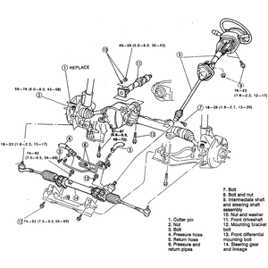
- Remove the rack and pinion assembly mounting bracket bolts and the front
differential/joint shaft assembly mounting bolts.
- Slide the differential/joint shaft assembly rearward. Slide the rack and
pinion assembly rearward and turn it 90 degrees, then remove it from the left
side of the vehicle.
To install:
- Install the rack and pinion assembly from the left side of the vehicle,
turn it 90 degrees and move it forward into position. Install the mounting
bolts and tighten, in sequence, to 54–69 ft. lbs. (74–93 Nm).
- Move the differential/joint shaft assembly forward, install the mounting
bolts and tighten to 49–72 ft. lbs. (67–97 Nm).
- Install the driveshaft, aligning the marks made during removal.
- Working inside the vehicle, move the steering column and intermediate shaft
forward to engage the intermediate shaft with the pinion shaft. Install and
tighten the steering column nuts and bolts to 12–17 ft. lbs. (16–23
Nm). Install the lower panel and column cover.
- Install the pinch bolt in the intermediate shaft-to-pinion shaft coupling
and tighten to 13–20 ft. lbs. (18–26 Nm).
- Install the pressure and return lines on the rack and pinion assembly. Connect
the pressure and return hoses to the lines.
- Position the tie rod end studs in the knuckles and install the nuts. Tighten
the nuts to 43–58 ft. lbs. (59–78 Nm) and install new cotter pins.
- Install the splash shield and the wheel and tire assemblies. Lower the vehicle
and bleed the power steering system.
| Fig. 4: Rack and pinion mounting, exploded view — 4WD

|


