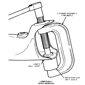
| Fig. 1: 2WD ball joint removal — 4WD
similar

|
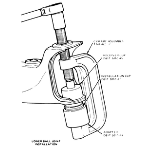
| Fig. 2: 2WD ball joint installation — 4WD
similar

|
NOTE: The ball joints are arranged such that if the upper ball
joint is to be removed, the lower ball joint must be removed first. Conversely,
on rear wheel drive vehicles, the upper ball joint must be installed first,
before the lower ball joint. On 4WD vehicles, when installing the upper ball
joint, the lower ball joint must be installed first. Failure to install the
ball joints in the correct order will result in a lack of clearance for the
installation tool.
- Remove the steering knuckle.
- Place knuckle in vise and remove snapring from bottom ball joint socket
if so equipped.
- Assemble the C-frame, T74P-4635-C, forcing screw, D79T-3010-AE and ball
joint remover T83T-3050-A or equivalent on the lower ball joint.
- Turn forcing screw clockwise until the lower ball joint is removed from
the steering knuckle.
- Repeat these steps for the upper ball joint.
NOTE: Always remove the lower ball joint first
To install:
- Clean the steering knuckle bore and insert lower ball joint in knuckle as
straight as possible. The lower ball joint doesn't have a cotter pin hole
in the stud.
- Assemble the C-frame, T74P-4635-C, forcing screw, D790T-3010-AE, ball joint
installer, T83T-3050-A and receiver cup T80T-3010-A3 or equivalent tools,
to install the upper ball joint (on rear wheel drive) or the lower ball joint
(on 4WD).
- Turn the forcing screw clockwise until the upper (rear wheel drive) or lower
(4WD) ball joint is firmly seated.
NOTE: If the ball joint cannot be installed to the proper
depth, realignment of the receiver cup and ball joint installer will be
necessary.
- Repeat these steps for the remaining ball joint.
- Be sure to install the snapring on the lower ball joint.
- Install the steering knuckle.
The ball joints on rear wheel drive MPV and all 1998 B Series Pick-up models
are integral with the control arms. If the ball joint is defective, the entire
control arm must be replaced. Refer to the appropriate control arm removal and
installation procedures later in the section.
- Raise and safely support the vehicle. Remove the wheel and tire assembly.
- Disconnect the sway bar from the lower control arm.
- Remove the cotter pin and nut from the lower ball joint stud. Separate the
ball joint from the knuckle.
- Remove the 2 upper bolts, one through-bolt and remove the ball joint.
To install:
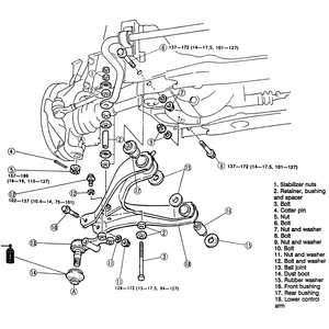
- Install the ball joint to the lower control arm. Tighten the two upper ball
joint-to-control arm bolts and washers to 75–101 ft. lbs. (102–137
Nm). Tighten the through-bolt and nut to 94–127 ft. lbs. (128–172
Nm).
- Install the ball stud into the steering knuckle. Torque the nut to 115–137
ft. lbs. (157–186 Nm) and install a new cotter pin.
- Connect the sway bar to the lower control arm.
- Install the wheel and tire assembly and lower the vehicle.
| Fig. 3: Ball joint and lower control arm assembly,
exploded view — 4WD

|
Ripped ball joint dust boots can be replaced. Replacement of the ball joint
dust boot is accomplished by removing the lower control arm from the vehicle
and chiseling the off old boot. Coat the inside of the new dust boot with lithium
grease and press it into the ball joint using the proper tool. Check the ball
joint stud threads for damage and repair as necessary. Check the ball joint
preload and install the lower control arm by reversing the removal procedure.

