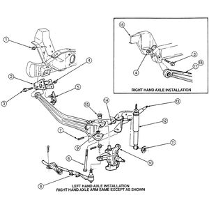
| Fig. 1: Exploded view of the front I-beam axle assembly

|
- Raise and safely support the vehicle. Remove the front wheel spindle. Remove
the front spring. Remove the front stabilizer bar, if equipped.
- Remove the spring lower seat from the radius arm, and then remove the bolt
and nut that attaches the stabilizer bar bracket, if equipped, and the radius
arm to the (I-Beam) front axle.
- Remove the axle-to-frame pivot bracket bolt and nut.
To install:
- Position the axle to the frame pivot bracket and install the bolt and nut
finger tight.
- Position the opposite end of the axle to the radius arm, install the attaching
bolt from underneath through the bracket, the radius arm and the axle. Install
the nut and tighten to 188–254 ft. lbs. (255–345 Nm).
- Install the spring lower seat on the radius arm so that the hole in the
seat indexes over the arm-to-axle bolt.
- Install the front spring.
NOTE: Lower the vehicle on its wheels or properly support
the vehicle at the front springs before tightening the axle pivot bolt and
nut.
- Tighten the axle-to-frame pivot bracket bolt to 111–148 ft. lbs. (150–200
Nm).
- Install the front wheel spindle.
The I-beam axle is part of the front drive axle assembly. Refer to Section
7 for front drive axle housing removal and installation procedures.

