Previous Next

REMOVAL & INSTALLATION

1998 B Series Pick-up

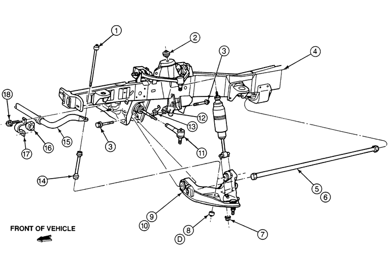
Fig. 1: Exploded view of the lower control arm assembly — 4WD shown, rear wheel drive does not have torsion bars, but has coil springs over the shock absorbers

NOTE: To remove the lower control arm, the torsion bar must be removed. Anytime the torsion bar is disturbed, the ride height must be checked and adjusted.

  1. Position the steering wheel to the on-center position. Loosen the wheel lug nuts.
  2. Raise and safely support the vehicle.
  3. Remove the wheel lug nuts and wheel.
  4. Disconnect the stabilizer bar link bolt from the lower control arm.
  5. Remove the front shock absorber.
  6. If 4WD, remove the torsion bar. If rear wheel drive, remove the coil spring.
  7. Remove the lower ball joint retaining nut cotter pin and loosen the nut but do not remove it.
  8. Disconnect the lower ball joint stud from the steering knuckle using a jawed puller, such as Pitman Arm Puller T64P-3590-F, or equivalent.

    WARNING
    Fasten a support, either out of a block of wood or wire wrapped around the frame, and support the weight of the steering knuckle/brake assembly. Do not allow the steering knuckle/brake assembly to hang from the upper ball joint as this may damage the joint.

  9. Position a jack under the lower control arm then remove the lower ball joint retaining nut.
  10. Raise the lower control arm until the lower ball joint stud is free from the steering knuckle.
  11. Remove the two nuts and bolts retaining the lower arm pivot points to the frame crossmember.
  12. Remove the lower control arm from the frame pockets. Some careful prying may ease the removal of the arm.

    To install:

  13. Inspect the lower ball joint, boot and pivot bushings. If any inspected components are worn or damaged, the entire control arm must be replaced.

    NOTE: Do not tighten the lower control arm mounting bolts to the final torque until the end of the installation procedure.

  14. Position the lower control arm pivot points into the frame and crossmember pockets. Install the bolts and nuts and snug the bolts.
  15. Position a jack under the lower control arm.
  16. If 4WD, install the torsion bar. If rear wheel drive, install the coil spring.
  17. Raise the lower control arm to allow the lower ball joint stud to be inserted into the steering knuckle.
  18. Lower the control arm assembly and ensure that the lower ball joint stud protrudes through the steering knuckle bore.
  19. Install the lower ball joint attaching nut and tighten to 83–113 ft. lbs. (113–153 Nm). Install a new cotter pin, advancing (tightening) the nut as required. Never loosen the retaining nut in order to install the cotter pin.
  20. Install the shock absorber.
  21. Install the wheel and snug the lug nuts.
  22. Lower the vehicle and tighten the lug nuts to 100 ft. lbs. (135 Nm).

    NOTE: The lower control arm-to-frame bolts must be tightened with the weight of the vehicle resting on the wheels. If clearance permits, allow the vehicle to sit on the ground while tightening the bolts.

  23. If necessary, raise the vehicle again and position either car ramps under the wheels or jackstands on the lower control arms, as close to the wheels as possible.
  24. Tighten the control arm-to-frame bolts to 111–148 ft. lbs. (150–200 Nm).
  25. Lower the vehicle.
  26. Check and adjust the ride height.
  27. While it should not be necessary, have the wheel alignment checked by a professional shop.
MPV Models
REAR WHEEL DRIVE
  1. Raise and safely support the vehicle. Remove the wheel and tire assembly.
  2. Remove the brake caliper and support it aside with mechanics wire, do not let it hang by the brake hose.

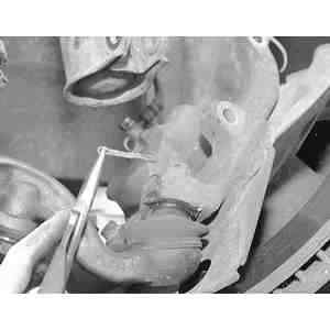
    Fig. 2: Remove and discard the lower ball joint stud cotter pin

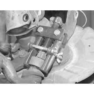
    Fig. 3: Using a ball joint separator tool, separate the steering knuckle from the lower ball joint

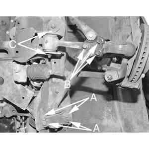
    Fig. 4: After separating the ball joint from the steering knuckle and sway bar link from the lower control arm, remove the 3 compression rod-to-control arm bolts (B), control arm bushing nut and through bolt (C) and 4 tailing arm-to-frame rail bolts (A)

  3. Remove the nuts, bolts, spacer, washers and bushings and remove the compression rod from the lower control arm and chassis and disconnect the stabilizer bar from the lower control arm.
  4. Remove the cotter pin and nut and separate the tie rod end from the knuckle.
  5. Remove the bolts and nuts and disconnect the strut from the knuckle.
  6. Remove the cotter pin and nut from the lower ball joint stud and separate the lower ball joint from the knuckle.
  7. Remove the mounting bolt and nut and remove the lower control arm from the vehicle.

    To install:

  8. Position the lower control arm to the chassis and install the bolt and nut, but do not tighten at this time.
  9. Install the knuckle to the lower control arm. Tighten the lower ball joint stud nut to 87–115 ft. lbs. (118–156 Nm) and install a new cotter pin.
  10. Connect the strut to the knuckle and tighten the attaching bolts and nuts to 69–86 ft. lbs. (94–116 Nm).
  11. Connect the tie rod end to the knuckle. Tighten the tie rod end stud nut to 43–58 ft. lbs. (59–78 Nm) and install a new cotter pin.
  12. Install the compression rod to the lower control arm and chassis. Tighten the compression rod-to-lower control arm mounting bolts to 76–93 ft. lbs. (103–126 Nm) and the compression rod bushing-to-chassis bolts to 61–76 ft. lbs. (83–103 Nm). Install the compression rod nut but do not tighten at this time.

    NOTE: The left-hand compression rod nut has left-hand threads.

  13. Connect the stabilizer bar to the control arm with the bolt, washers, bushings, spacer and nuts. Tighten the nuts so 0.24 in. (6mm) of thread is exposed at the end of the bolt.
  14. Install the caliper and the wheel and tire assembly. Lower the vehicle.
  15. With the vehicle unloaded, tighten the lower control arm-to-chassis bolt and nut to 94–108 ft. lbs. (146–172 Nm). Tighten the compression rod nut to 108–126 ft. lbs. (147–171 Nm).
  16. Lower the vehicle.
  17. Check the front end alignment.
4-WHEEL DRIVE
  1. Raise and safely support the vehicle. Remove the wheel and tire assembly.
  2. Remove the bolt, retainers, bushings, spacer and nuts and disconnect the stabilizer bar from the lower control arm.
  3. Remove the cotter pin and nut from the lower ball joint stud. Separate the ball joint from the knuckle.
  4. Remove the lower control arm-to-chassis nuts and bolts and remove the lower control arm.

    To install:

  5. Position the lower control arm to the chassis and install the bolts and nuts. Do not tighten at this time.
  6. Connect the lower ball joint to the knuckle and tighten the ball joint stud nut to 116–137 ft. lbs. (157–186 Nm). Install a new cotter pin.
  7. Install the bolt, retainers, bushings, spacer and nuts and connect the stabilizer bar to the lower control arm. Tighten the nuts so 0.20–0.28 in. (5–7mm) of thread is exposed at the end of the bolt.
  8. Install the wheel and tire assembly and lower the vehicle. With the vehicle unloaded, tighten the lower control arm-to-chassis nuts and bolts to 102–126 ft. lbs. (138–171 Nm).
  9. Lower the vehicle.
  10. Check the front end alignment.

Previous Next