- As required, raise and safely support the vehicle using jackstands.
- Remove the cotter pin and nut from the drag link ball stud at the pitman
arm.
- Remove the drag link ball stud from the pitman arm using pitman arm removal
tool T64P-3590-F or equivalent.
- Remove the pitman arm retaining nut and washer. Remove the pitman arm from
the steering gear sector shaft using tool T64P-3590-F or equivalent.
To install:
- Installation is the reverse of the removal procedure. Torque the pitman
arm attaching washer and nut to 170–228 ft. lbs. (230–310 Nm).
Torque the drag link ball stud nut to 51–73 ft. lbs. (70–100 Nm)
and install a new cotter pin.
- Check and adjust front end alignment, as required.
- Raise and support the vehicle using jackstands. Be sure that the front wheels
are in the straight ahead position.
- Remove the nut and cotter pin from the ball stud on the drag link. Remove
the ball stud from the drag link using pitman arm removal tool T64P-3590-F
or equivalent.
- Loosen the bolts on the tie rod adjusting sleeve. Be sure to count and record
the number of turns it takes to remove the tie rod from the tie rod adjusting
sleeve. Remove the tie rod from the vehicle.
| Fig. 1: To remove the tie rod end, first remove the
cotter pin and discard it. A new pin will be used for installation
|
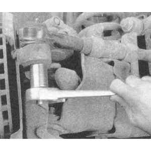
| Fig. 2: Loosen and remove the tie rod end retaining
nut . . .
|
| Fig. 3: . . . then, using a jawed puller, loosen
the tie rod stud-to-steering knuckle connection
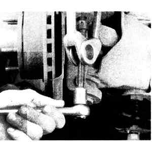
|
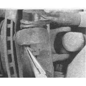
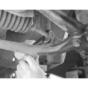
| Fig. 4: Loosen the tie rod sleeve clamp bolts . .
.
|
| Fig. 5: . . . and before unthreading the tie rod
from the sleeve, make an installation mark on the threads
|
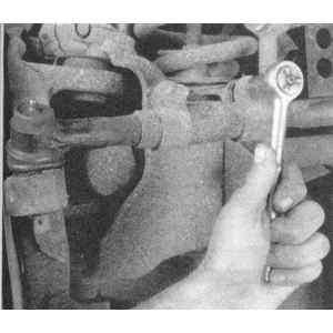
| Fig. 6: Lift the tie rod end out of the steering
knuckle bore . . .
|
| Fig. 7: . . . and unthread the tie rod end from the
adjusting sleeve
|
To install:
- Install the tie rod in the tie rod sleeve in the same number of turns it
took to remove it. Torque the tie rod adjusting sleeve nuts to 30–42
ft. lbs. (40–57 Nm).
- Be sure that the adjusting sleeve clamps are pointed down ±45°. Tighten
the tie rod ball stud to drag link retaining bolt to 51–73 ft. lbs.
(70–100 Nm). Install a new cotter pin.
- Check and adjust front end alignment, as required.
- Raise and support the vehicle using jackstands. Be sure that the front wheels
are in the straight ahead position.
- Remove the nuts and cotter pins from the ball stud at the pitman arm and
steering tie rod. Remove the ball studs from the linkage using pitman arm
removal tool T64P-3590-F or equivalent.
- Loosen the bolts on the drag link adjusting sleeve. Be sure to count and
record the number of turns it takes to remove the drag link.
To install:
- Install the drag link in the same number of turns it took to remove it.
Tighten the adjusting sleeve nuts to 30–42 ft. lbs. (40–57 Nm).
Be sure that the adjusting sleeve clamps are pointed down ±45°.
- Position the drag link ball stud in the pitman arm. Position the steering
tie rod ball stud in the drag link. With the vehicle wheels in the straight
ahead position install and torque the nuts to 51–73 ft. lbs. (70–100
Nm). Install a new cotter pin.
- Check and adjust front end alignment, as required.
WARNING
If equipped, always turn off the Automatic Ride Control (ARC) service switch
before lifting the vehicle off of the ground. Failure to do so could damage
the ARC system components. Refer to Section 1 for jacking procedures.
- Position the front wheels in the straight ahead position.
- Raise and safely support the vehicle, as necessary.
- Remove and discard the outer tie rod end retaining nut cotter pin.
- Remove the nut and install a puller to separate the tie rod end from the
steering knuckle.
- Hold the tie rod end with a wrench and loosen the jam nut.
- Mark the exact position of the outer tie rod on the inner tie rod threads.
Grip the tie rod end with a pair of pliers and unscrew the outer end from
the inner tie rod.
To install:
- Ensure that the inner tie rod threads are clean.
- Thread the outer tie rod end onto the inner tie rod to the same location
as marked earlier.
- Install the out tie rod end stud into the steering knuckle then install
and tighten the attaching nut to 57–77 ft. lbs. (77–104 Nm). Install
new cotter pins, advancing (tightening) the nut as required. NEVER loosen
the nut to install the cotter pin.
- Tighten the jam nut, while holding the outer tie rod, to 50–68 ft.
lbs. (68–92 Nm).
- Have the toe alignment checked and adjusted by a professional shop.
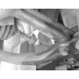
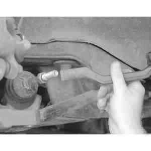
| Fig. 8: Using a backup wrench, loosen the jam nut from
the tie rod
|
| Fig. 9: Matchmark the location of the tie rod end on
the tie rod. This will help during installation
|
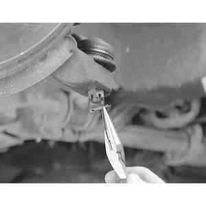
| Fig. 10: Remove and discard the cotter pin from tie rod
ball stud
|
- Raise and support the front end on jackstands.
- Remove the wheels.
- Matchmark the tie rod end and tie rod and loosen the locknut.
- Loosen the tie rod end ball stud nut and separate the tie rod end from the
knuckle arm with a separator tool.
- Unscrew the tie rod end, counting the number of turns until it's off, for
installation purposes.
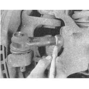
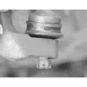
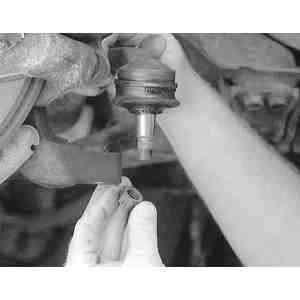
| Fig. 11: Install the castle nut onto the end of the
ball stud to prevent the stud from "mushrooming" during removal
|
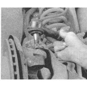
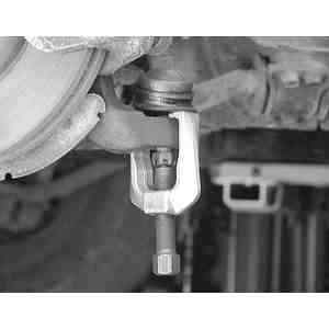
| Fig. 12: Using a puller tool with the castle nut
on the end of the ball stud, separate the tie rod end ball joint from
the steering knuckle
|
| Fig. 13: Remove the castle nut and pull the tie rod
end ball stud straight out of the steering knuckle
|
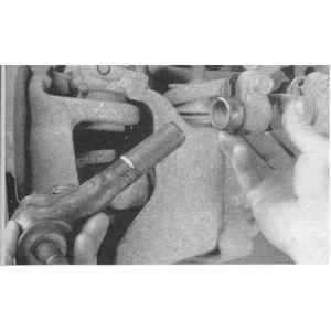
| Fig. 14: Count the number of turns required to remove
the tie rod end from the tie rod. This will help during the installation
process
|
To install:
- Install the tie rod end onto the tie rod the same number of turns that it
took to remove it. Tighten the locknut to 51–57 ft. lbs. (69–78
Nm).
- Install the ball stud into the steering knuckle. Tighten the ball stud nut
to 44–57 ft. lbs. (59–78 Nm) and install the cotter pin.
- Lower the vehicle and install a new cotter pin. Always advance the nut to
align the cotter pin hole. Never back it off. Check the front alignment.

