Previous Next

REMOVAL & INSTALLATION

Navajo and 1994–97 B Series Pick-up
REAR WHEEL DRIVE

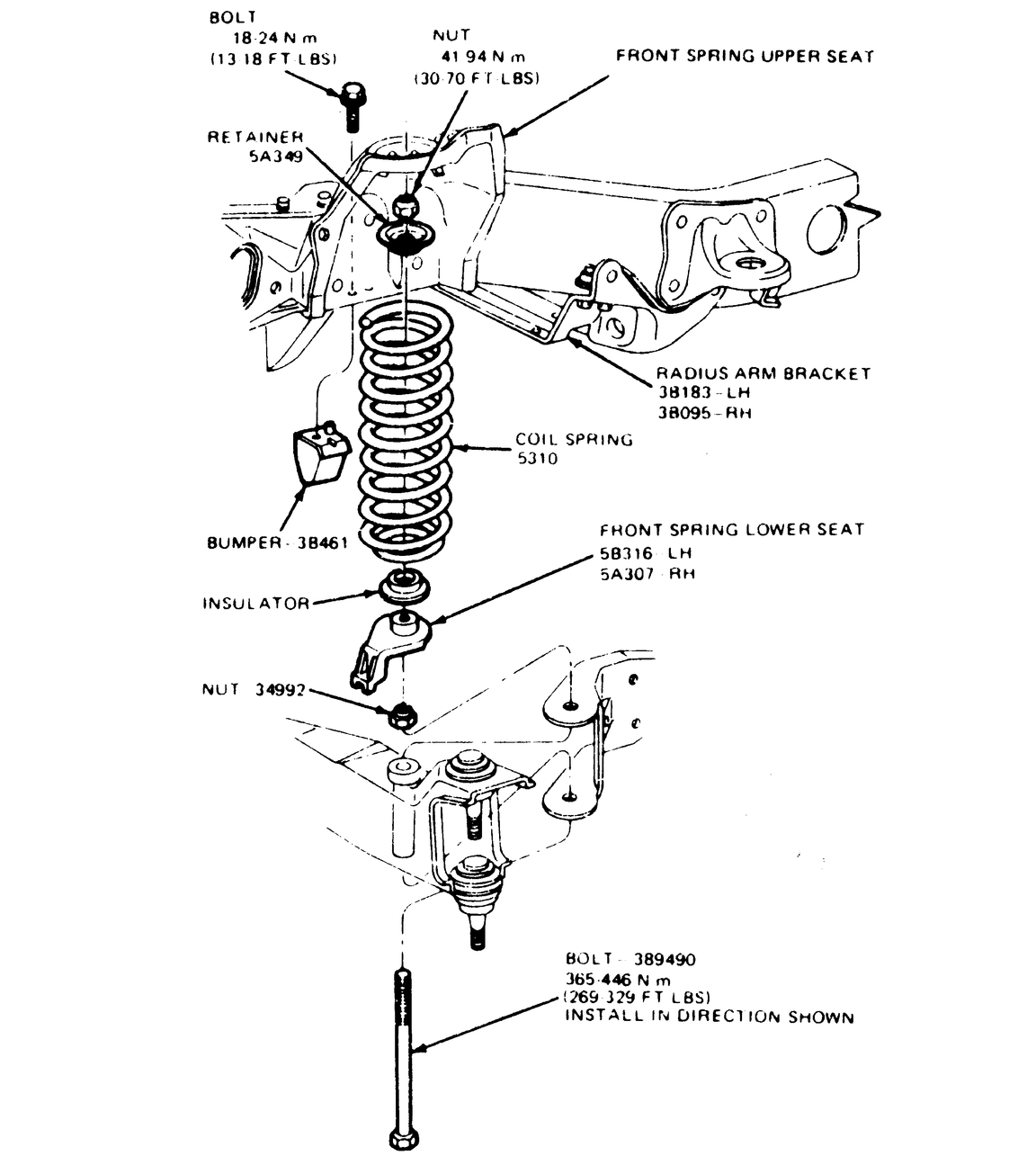
Fig. 1: Exploded view of the 1994–97 B Series Pick-up coil spring and related parts

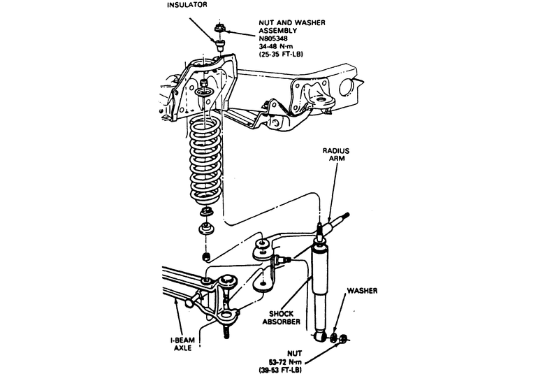
Fig. 2: Exploded view of the 1994 Navajo coil spring and related parts

  1. Raise the front of the vehicle and place jackstands under the frame and a jack under the axle.

    WARNING
    The axle must not be permitted to hang by the brake hose. If the length of the brake hoses is not sufficient to provide adequate clearance for removal and installation of the spring, the disc brake caliper must be removed from the spindle. A Strut Spring Compressor, T81P-5310-A or equivalent may be used to compress the spring sufficiently, so that the caliper does not have to be removed. After removal, the caliper must be placed on the frame or otherwise supported to prevent suspending the caliper from the caliper hose. These precautions are absolutely necessary to prevent serious damage to the tube portion of the caliper hose assembly!

  2. Disconnect the shock absorber at the lower shock stud. Remove the nut securing the lower retainer to spring seat. Remove the lower retainer.
  3. Lower the axle as far as it will go without stretching the brake hose and tube assembly. The axle should now be unsupported without hanging by the brake hose. If not, then either remove the caliper or use Strut Spring Compressor Tool, T81P-5310-A or equivalent. Remove the spring.
  4. If there is a lot of slack in the brake hose assembly, a pry bar can be used to lift the spring over the bolt that passes through the lower spring seat.
  5. Rotate the spring so the built-in retainer on the upper spring seat is cleared.
  6. Remove the spring from the vehicle.

    To install:

  7. If removed, install the bolt in the axle arm and install the nut all the way down. Install the spring lower seat and lower insulator. On the 1994 Navajo, also install the stabilizer bar mounting bracket and spring spacer.
  8. With the axle in the lowest position, install the top of the spring in the upper seat. Rotate the spring into position.
  9. Lift the lower end of the spring over the bolt.
  10. Raise the axle slowly until the spring is seated in the lower spring upper seat. Install the lower retainer and nut.
  11. Connect the shock absorber to the lower shock stud.
  12. Remove the jack and jackstands and lower vehicle.
FOUR WHEEL DRIVE

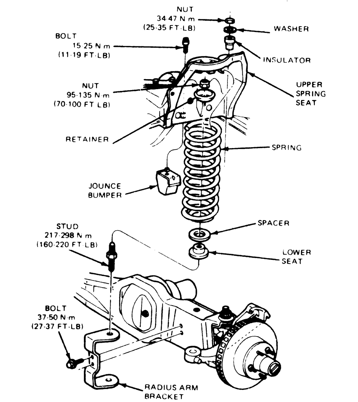
Fig. 3: Coil spring and related parts

  1. Raise the vehicle and install jackstands under the frame. Position a jack beneath the spring under the axle. Raise the jack and compress the spring.
  2. Remove the nut retaining the shock absorber to the radius arm. Slide the shock out from the stud.
  3. Remove the nut that retains the spring to the axle and radius arm. Remove the retainer.
  4. Slowly lower the axle until all spring tension is released and adequate clearance exists to remove the spring from its mounting.
  5. Remove the spring by rotating the upper coil out of the tabs in the upper spring seat. Remove the spacer and the seat.

    WARNING
    The axle must be supported on the jack throughout spring removal and installation, and must not be permitted to hang by the brake hose. If the length of the brake hose is not sufficient to provide adequate clearance for removal and installation of the spring, the disc brake caliper must be removed from the spindle. After removal, the caliper must be placed on the frame or otherwise supported to prevent suspending the caliper from the brake line hose. These precautions are absolutely necessary to prevent serious damage to the tube portion of the caliper hose assembly!

  6. If required, remove the stud from the axle assembly.

    To install:

  7. If removed, install the stud on the axle and torque to 190–230 ft. lbs. Install the lower seat and spacer over the stud.
  8. Place the spring in position and slowly raise the front axle. Ensure springs are positioned correctly in the upper spring seats.
  9. Position the spring lower retainer over the stud and lower seat and torque the attaching nut to 70–100 ft. lbs.
  10. Position the shock absorber to the lower stud and install the attaching nut. Tighten the nut to 41–63 ft. lbs. Lower the vehicle.
1998 B Series Pick-up (rear wheel drive only)
  1. Raise and safely support the vehicle.
  2. Remove the front wheel.
  3. Remove the front disc brake rotor shield.
  4. Remove the front shock absorber.
  5. Remove the front sway bar link nut.

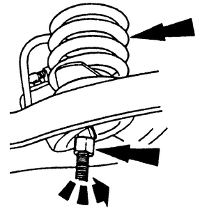
    Fig. 4: Use a coil spring compressor tool to compress the coil spring

  6. Compress the front coil spring using a spring comressor tool.
  7. Remove the lower ball joint cotter pin and castle nut.
  8. Using a pitman arm puller or equivalent puller tool, separate the lower ball joint from the front wheel steering knuckle.
  9. Position the knuckle to one side and remove the coil spring.

    To install:

    Fig. 5: The end of the coil spring must cover the first hole and should not be visible in the second hole

  10. Install the coil spring (with spring compressor tool installed) into the lower control arm. Be sure that the end of the coil spring covers the first hole on the lower control arm and is not visible in the second hole.
  11. Install the front wheel spindle into the lower ball joint and install the castle nut. Tighten the castle nut to 83–113 ft. lbs. (113–153 Nm).
  12. Install a new cotter pin. Be sure to install the cotter pin with the loop of the pin pointing to the tire or damage to the tire could result.
  13. Install the front sway bar link nut and tighten to 15–21 ft. lbs. (21–29 Nm).
  14. Remove the coil spring compressor tool.
  15. Install the shock absorber.
  16. Install the front disc brake rotor shield.
  17. Install the front wheel.
  18. Lower the vehicle.

Previous Next