All models use a self-adjusting parking brake cable assembly. However, in order
to remove any of the cables or components, the following procedures must be
followed.
| Fig. 1: With the parking brake released, insert the pin
into the brake control assembly as shown to lock the cable tension spring
|
Method 1:
- Place the parking brake cable control in the released position.
- Have an assistant pull on the intermediate brake cable while you insert
a 5⁄32 in.
(4mm) diameter steel pin (or drill bit) into the hole provided in the parking
brake control assembly.
- To release the cable tension, pull out the lock pin from the control assembly.
Method 2:
For relieving tension from the rear cables only.
- Pull backwards on the rear cable and conduit about 1.0–2.0 in. (25–50mm)
and place a clamp on the parking brake cable and conduit behind the rear crossmember.
WARNING
Ensure that you do not damage the nylon coating on the cable.
- To release the cable tension, remove the clamp holding the rear cable to
the crossmember.
| Fig. 2: Exploded view of the parking brake control assembly
mounting
|
In the event that one of the cables has broken, or the cable tension release
procedures were not followed perform the following procedures:
- Remove the parking brake control assembly.
| Fig. 3: Engage the coil spring to the tab on the
adjusting wheel
|
- Engage the coil spring to the tab on the adjusting wheel in the control
assembly.
- Ensure the control assembly is in the released position.
| Fig. 4: Slip the front parking brake cable around
the pulley and insert the cable end to the ratchet plate
|
- Slip a spare front parking brake (or remove you existing one) cable around
the pulley and insert the cable end into the pivot hole in the ratchet plate.
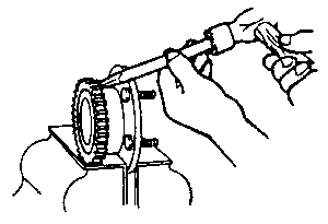
| Fig. 5: While stepping on the cable end, pull upwards
on the control assembly then install the lock pin when the holes align
|
- Position the free end of the parking brake cable on the floor and step on
it, or clamp it in a vise.
- Pull on the control assembly, holding the mounting bracket tightly against
the body of the control, until the cable tension rotates the cable track assembly
so that the (lock pin) 5⁄32 in.
(4mm) diameter steel pin (or drill bit) can be fully seated through the plate.
- Insert the lock pin so that the assembly is in the "cable released" position.
- Install the parking brake control lever.
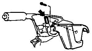
| Fig. 6: Adjust the parking brake cable at the lever
|
- Remove the parking brake lever cover.
- Remove the adjusting nut clip and turn the adjusting nut at the front of
the parking cable to adjust.
- After adjustment, with the ignition switch in the ON position,
pull the parking brake lever one notch. Check that the parking brake warning
light illuminates.
- When the cable is properly adjusted, the lever should move 3–6 notches.
- Replace the adjusting nut clip.

