CAUTION
Older brake pads or shoes may contain asbestos, which has been determined to
be a cancer causing agent. Never clean the brake surfaces with compressed air!
Avoid inhaling any dust from any brake surface! When cleaning brake surfaces,
use a commercially available brake cleaning fluid.
- Raise and support the vehicle and remove the wheel and brake drum from the
wheel to be worked on.
NOTE: If you have never replaced the brakes on a car before
and you are not too familiar with the procedures involved, only disassemble
and assemble one side at a time, leaving the other side intact as a reference
during reassembly.
- Install a clamp over the ends of the wheel cylinder to prevent the pistons
of the wheel cylinder from coming out, causing loss of fluid.
- Contract the brake shoes by pulling the self-adjusting lever away from the
starwheel adjustment screw and turn the starwheel up and back until the pivot
nut is drawn onto the starwheel as far as it will come.
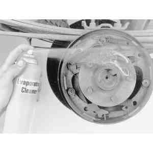
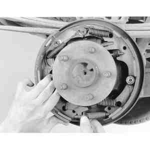
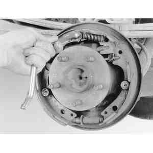
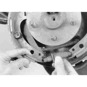
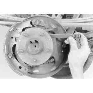
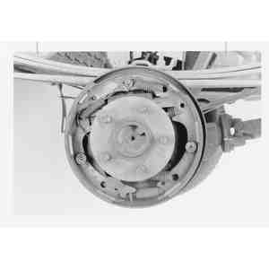
| Fig. 1: Clean the brake shoe assemblies with a liquid
cleaning solution, NEVER with compressed air
|
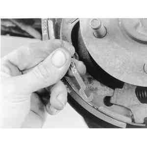
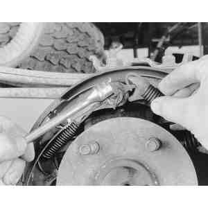
| Fig. 2: To begin remove the brake shoes, pull the
adjuster cable towards the shoe . . .
|
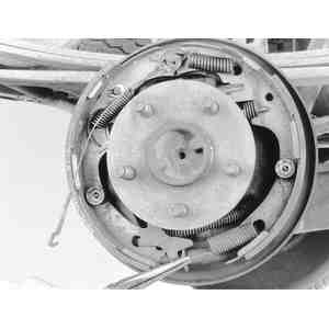
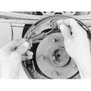
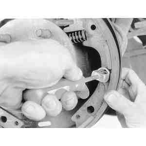
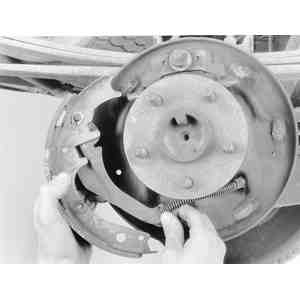
| Fig. 3: . . . and disconnect the pivot hook from
the adjusting lever. Wind the starwheel all the way in
|
- Pull the adjusting lever, cable and automatic adjuster spring down and toward
the rear to unhook the pivot hook from the large hole in the secondary shoe
web. Do not attempt to pry the pivot hook from the hole.
- Remove the automatic adjuster spring and the adjusting lever.
- Remove the primary shoe-to-anchor spring with a brake tool. (Brake tools
are very common and are available at auto parts stores). Remove the secondary
shoe-to-anchor spring and unhook the cable anchor. Remove the anchor pin plate.
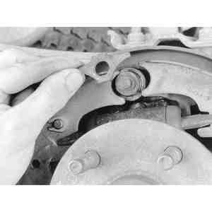
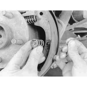
| Fig. 4: Disconnect the adjuster lever return spring
from the lever . . .
|
| Fig. 5: . . . and remove the spring and the lever
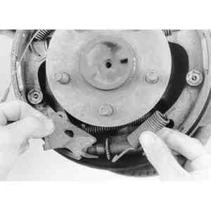
|
| Fig. 6: Next, using a brake spring removal tool .
. .
|
| Fig. 7: . . . disconnect the primary brake shoe return
spring from the anchor pin
|
| Fig. 8: Repeat the procedure and remove the secondary
return spring, adjuster cable and its guide
|
| Fig. 9: Also remove the anchor pin plate
|
- Remove the cable guide from the secondary shoe.
- Remove the shoe hold-down springs, shoes, adjusting screw, pivot nut, and
socket. Note the color of each hold-down spring for assembly. To remove the
hold-down springs, reach behind the brake backing plate and place one finger
on the end of one of the brake hold-down spring mounting pins. Using a pair
of pliers, grasp the washer-type retainer on top of the hold-down spring that
corresponds to the pin that you are holding. Push down on the pliers and turn
them 90°to align the slot in the washer with the head on the spring mounting
pin. Remove the spring and washer retainer and repeat this operation on the
hold-down spring on the other shoe.
- Remove the parking brake link and spring. Disconnect the parking brake cable
from the parking brake lever.
- After removing the rear brake secondary shoe, disassemble the parking brake
lever from the shoe by removing the retaining clip and spring washer.
| Fig. 10: Pull the bottoms of the shoes apart and
remove the adjuster screw assembly
|
| Fig. 11: Press in the hold-down springs while holding
in on the nail from behind, then turn the cup 90º . . .
|
| Fig. 12: . . . and release to remove the hold-down
spring. Pull the nail out from the backing plate
|
| Fig. 13: Remove the primary (front) brake shoe from
the backing plate . . .
|
| Fig. 14: . . . and the parking brake strut as well
|
| Fig. 15: Remove the secondary shoe hold-down, pull
the shoe out then press up on the cable spring . . .
|
| Fig. 16: . . . and disconnect the parking brake cable
from its lever by pulling it from the slot

|
To assemble and install the brake shoes:
| Fig. 17: Lightly apply the proper grade of lubricant
to the points shown on the backing plate

|
- Assemble the parking brake lever to the secondary shoe and secure it with
the spring washer and retaining clip.
- Apply a light coating of Lubriplate® at the points where the brake
shoes contact the backing plate.
- Position the brake shoes on the backing plate, and install the hold-down
spring pins, springs, and spring washer-type retainers. Install the parking
brake link, spring and washer. Connect the parking brake cable to the parking
brake lever.
- Install the anchor pin plate, and place the cable anchor over the anchor
pin with the crimped side toward the backing plate.
- Install the primary shoe-to-anchor spring with the brake tool.
- Install the cable guide on the secondary shoe web with the flanged holes
fitted into the hole in the secondary shoe web. Thread the cable around the
cable guide groove.
- Install the secondary shoe-to-anchor (long) spring. Be sure that the cable
end is not cocked or binding on the anchor pin when installed. All of the
parts should be flat on the anchor pin. Remove the wheel cylinder piston clamp.
- Apply Lubriplate® to the threads and the socket end of the adjusting
starwheel screw. Turn the adjusting screw into the adjusting pivot nut to
the limit of the threads and then back off 1⁄2 turn.
NOTE: Interchanging the brake shoe adjusting screw assemblies
from one side of the vehicle to the other would cause the brake shoes to
retract rather than expand each time the automatic adjusting mechanism operated.
To prevent this, the socket end of the adjusting screw is stamped with an
R or an L for RIGHT or LEFT. The adjusting pivot nuts can be distinguished
by the number of lines machined around the body of the nut; one line indicates
left hand nut and 2 lines indicates a right hand nut.
- Place the adjusting socket on the screw and install this assembly between
the shoe ends with the adjusting screw nearest to the secondary shoe.
- Place the cable hook into the hole in the adjusting lever from the backing
plate side. The adjusting levers are stamped with an R (right)
or an L (left) to indicate their installation on the right
or left hand brake assembly.
- Position the hooked end of the adjuster spring in the primary shoe web and
connect the loop end of the spring to the adjuster lever hole.
- Pull the adjuster lever, cable and automatic adjuster spring down toward
the rear to engage the pivot hook in the large hole in the secondary shoe
web.
- After installation, check the action of the adjuster by pulling the section
of the cable between the cable guide and the adjusting lever toward the secondary
shoe web far enough to lift the lever past a tooth on the adjusting screw
starwheel. The lever should snap into position behind the next tooth, and
release of the cable should cause the adjuster spring to return the lever
to its original position. This return action of the lever will turn the adjusting
screw starwheel one tooth. The lever should contact the adjusting screw starwheel
one tooth above the center line of the adjusting screw.
| Fig. 18: Exploded view of a typical brake adjuster
assembly
|
| Fig. 19: The return spring and adjuster correctly
installed
|
| Fig. 20: Correct adjuster cable routing, driver's
side shown
|
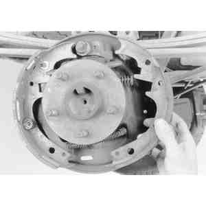
| Fig. 21: View of the rear drum brake shoes completely
assembled to the backing plate
|
If the automatic adjusting mechanism does not perform properly, check
the following:
- Check the cable end fittings. The cable ends should fill or extend slightly
beyond the crimped section of the fittings. If this is not the case, replace
the cable.
- Check the cable guide for damage. The cable groove should be parallel to
the shoe web, and the body of the guide should lie flat against the web. Replace
the cable guide if this is not so.
- Check the pivot hook on the lever. The hook surfaces should be square with
the body on the lever for proper pivoting. Repair or replace the hook as necessary.
- Make sure that the adjusting screw starwheel is properly seated in the notch
in the shoe web.